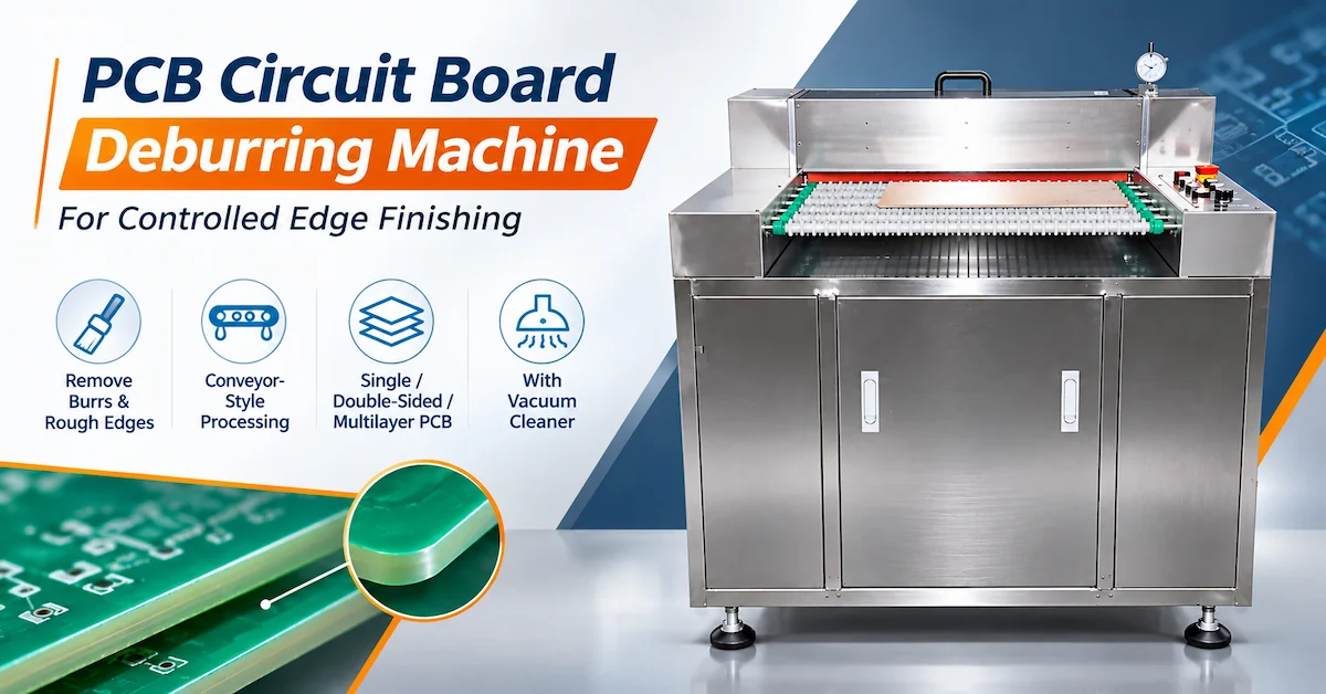




A PCB chamfering machine helps printed circuit board manufacturers create controlled corner profiles, reduce sharp edges, and improve the consistency of board handling during production.
For factories processing FR4 panels, LED circuit boards, and other suitable rigid PCB materials, poorly finished corners can interfere with fixtures, create handling difficulties, and introduce additional rework before assembly or packaging.
The CHIKIN CNC CK-YJ50 is a PCB corner grinding and chamfering machine with a published 1.5kW power rating, five groups of ten-tooth combination diamond-ground rounded-corner knives, and a pneumatic operating requirement of 0.5–0.6MPa.
Its specifications also include a reference production efficiency of 100 panels per minute at a stated 1.6mm condition. However, the production conditions behind this figure require confirmation, and actual accepted output must be established through sample testing.
For industrial buyers, the key purchasing question is not simply whether a machine can round PCB corners. It is whether the equipment can consistently produce the required geometry without damaging the laminate or reducing manufacturing efficiency.
This guide explains the CK-YJ50's technical specifications, tool configuration, FR4 processing considerations, quality-control requirements, and factory acceptance procedures.
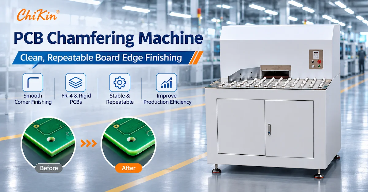
1. What Is a PCB Chamfering Machine?
A PCB chamfering machine is specialized equipment used to remove material from the edges or corners of printed circuit boards to create a specified finishing profile.
Depending on the machine and tooling, the process may produce an angled bevel, a rounded corner, or another controlled edge geometry.
These operations are related but not identical.
-
Chamfering typically creates an angled transition between surfaces.
-
Corner rounding produces a curved profile at a board corner.
-
Edge grinding removes material through controlled abrasive or cutting action.
-
Deburring removes unwanted projections left by previous machining processes.
The CK-YJ50 product specification identifies rounded-corner cutting tools, so its exact application should be evaluated as a PCB corner-grinding process rather than assuming it performs every possible edge-chamfering operation.
Why Do PCB Manufacturers Need Controlled Corner Finishing?
After routing, cutting, or other mechanical operations, PCB panels may have sharp corners, irregular edges, or exposed glass fibers.
These conditions can contribute to difficulties during subsequent handling.
A qualified corner-finishing process may help manufacturers:
-
Improve consistency between finished boards.
-
Reduce sharp corners during manual handling.
-
Prepare boards for trays, positioning fixtures, and assembly equipment.
-
Reduce variation caused by manual grinding.
-
Standardize defined corner profiles across production batches.
The objective is controlled geometry and acceptable quality—not simply maximum material removal.
2. Who Should Consider the CK-YJ50 PCB Corner Grinding Machine?
The CK-YJ50 is relevant to industrial buyers that need repeated corner treatment on suitable PCB formats.
| Target Customer | Application | Main Purchasing Concern |
|---|---|---|
| PCB fabrication factories | Rigid PCB corner finishing | Consistent corner dimensions |
| FR4 board manufacturers | Fiberglass laminate corner grinding | Fiber breakout and edge integrity |
| LED PCB manufacturers | Suitable LED board corner processing | Board geometry and material compatibility |
| Electronics assembly factories | Board preparation before assembly | Smooth handling and fixture fit |
| PCB prototyping workshops | Different board formats | Setup adjustment and flexibility |
| High-volume PCB factories | Repeated corner treatment | Accepted output and tool life |
| Industrial equipment buyers | Production-line investment | Quality, maintenance and total cost |
Which Applications May Not Be Suitable?
Not every circuit board should be processed using mechanical corner grinding.
Boards containing mounted components close to the working area, very thin flexible circuits, or sensitive copper features may require alternative processing methods.
Material compatibility and process suitability should be checked against actual board drawings and sample results.
For complex board outlines and internal slots, a PCB CNC drilling and routing machine may be more appropriate than a dedicated corner-finishing machine.
3. CHIKIN CNC CK-YJ50 Technical Specifications
The CK-YJ50 is presented as a floor-standing industrial PCB corner grinding machine.
Its supplied product photographs show a gray cabinet structure, a work surface with multiple support elements, a rear processing section, front access doors, and a side-mounted operator control panel.
These features are consistent with an industrial board-handling and finishing workstation.
CK-YJ50 Specification Table
| Technical Parameter | Published Specification |
|---|---|
| Model | CK-YJ50 |
| Equipment type | PCB corner grinding / chamfering machine |
| Processing range | 0–50mm |
| Reference work efficiency | 1.6mm × 100 panels/min |
| Published processing thickness | 0–50mm |
| Tool configuration | Five groups of ten-tooth combination diamond-ground rounded-corner knives |
| Working pressure | 0.5–0.6MPa |
| Working voltage | AC380V |
| Rated power | 1.5kW |
| Machine dimensions | 1105 × 1000 × 1350mm |
| Machine weight | Approximately 300kg |
Specifications are reproduced from the supplied CK-YJ50 product sheet and require final confirmation against the quoted equipment.
Important Specifications That Require Verification
Processing range and thickness: The source table lists 0–50mm in both fields. The precise meanings of these measurements are not explained, so buyers should not interpret them as a confirmed ability to process 50mm-thick FR4 panels.
Production efficiency: The value “1.6mm × 100 panels/min” is presented without a complete description of the test conditions. Confirm board dimensions, thickness, feeding arrangement, and whether the figure represents theoretical or accepted output.
Cutting tool configuration: The datasheet describes five groups of ten-tooth combination diamond-ground rounded-corner knives. Buyers should confirm the precise tool structure, material, replaceable parts, and available corner profiles.
These clarifications are especially important when preparing a technical RFQ.
4. How Do Rounded-Corner Knives Affect PCB Processing Quality?
The cutting-tool arrangement is a major factor in the performance of a PCB corner grinding machine.
The CK-YJ50 datasheet identifies multiple groups of rounded-corner tools.
However, the term “diamond-ground” should not automatically be interpreted as a specific diamond coating or polycrystalline diamond cutting material.
The actual tool construction must be confirmed.
Tooling Evaluation Checklist
| Tooling Factor | Buyer Verification | Why It Matters |
|---|---|---|
| Tool geometry | Available rounded-corner profiles | Determines finished corner shape |
| Cutting-edge condition | Surface finish and visible damage | Influences edge consistency |
| Tool material | Approved cutting material and construction | Affects wear characteristics |
| Tool groups | Arrangement and simultaneous processing capability | Influences production setup |
| Replacement parts | Tool codes and spare-part availability | Supports maintenance |
| Adjustment method | Tool setting and alignment procedure | Affects repeatability |
| Material compatibility | Suitability for actual FR4 or other PCB material | Reduces processing risk |
| Cleaning requirements | Tool-area access and debris removal | Supports stable operation |
Why Is Tooling Geometry Important?
Two cutters can remove a similar amount of material while producing different final corner profiles.
The correct geometry depends on the customer's mechanical drawing and intended downstream handling.
For example, a rounded corner may be required to fit a fixture or reduce a sharp external corner.
A bevel, by contrast, may be specified for an edge transition.
Buyers should not substitute a rounded corner for a specified chamfer without engineering approval.
The target geometry should be defined before choosing the tooling configuration.
5. How to Define PCB Corner Radius and Chamfer Quality
One of the most common procurement mistakes is requesting “smooth corners” without providing measurable acceptance criteria.
For production equipment, the required edge profile should be defined in engineering terms.
Corner Radius vs Chamfer
| Feature | Description | Typical Inspection |
|---|---|---|
| Rounded corner | Curved external corner geometry | Radius measurement |
| Angled chamfer | Straight beveled transition | Chamfer width and angle |
| Deburred edge | Unwanted burrs removed | Visual or magnified inspection |
| Ground edge | Surface material removed by grinding | Profile and surface-condition inspection |
What Should Be Included in the Drawing?
For a rounded-corner application, the drawing should identify the required corner radius and tolerance.
For a chamfer, it should specify the intended chamfer dimensions and angle.
Additionally, buyers should define:
-
Overall finished-board dimensions.
-
Permitted material removal.
-
Minimum clearance from copper features.
-
Maximum acceptable edge breakout.
-
Acceptable laminate condition.
-
Inspection method and sampling frequency.
The required geometry should come from the customer drawing, not from a generic machine specification.
Can Excessive Chamfering Damage a PCB?
Yes.
Excessive material removal may reduce board dimensions or affect nearby copper, solder mask, or laminate layers.
The correct process should create the specified profile while preserving the features required for the board's function and downstream assembly.
6. FR4 Corner Grinding: Main Processing Challenges
FR4 is a composite material containing fiberglass reinforcement and epoxy resin.
This construction creates different machining behavior from ordinary homogeneous plastics or metals.
During mechanical corner grinding, improper tool geometry, support, or process settings can contribute to fiber breakout and edge damage.
Common FR4 Edge Defects
| Defect | Possible Contributing Factor | Recommended Inspection |
|---|---|---|
| Fiber breakout | Unsuitable tooling or excessive cutting load | Magnified edge inspection |
| Uneven corner radius | Inconsistent alignment or tool setting | Profile measurement |
| Excessive material removal | Incorrect adjustment or positioning | Dimensional inspection |
| Chipped laminate | Tool condition or insufficient support | Visual and microscopic inspection |
| Exposed copper damage | Insufficient clearance from processing zone | Copper-edge inspection |
| Loose particles | Inadequate debris management | Cleanliness inspection |
| Inconsistent finish | Tool wear or changing process conditions | Repeated sample comparison |
Why Is Board Support Important?
If the panel moves during processing, the cutting tool may remove different amounts of material from different corners.
This can result in an inconsistent finished profile.
Stable positioning and controlled feed are therefore important considerations.
Buyers should ask how the CK-YJ50 supports and guides the board during processing, including how it handles different panel sizes and thicknesses.
7. How Does the CK-YJ50 Fit into PCB Manufacturing?
A PCB chamfering machine typically performs a finishing operation rather than the entire PCB outline-machining process.
A general workflow may include:
Step 1 — Board Preparation
Receive boards that require corner treatment and verify the material, dimensions, and specified finishing profile.
Step 2 — Workstation Setup
Confirm the machine configuration, guide positions, tooling condition, and applicable operating settings.
Step 3 — Board Loading
Position the board using the approved handling or feeding arrangement.
Step 4 — Corner Processing
The machine processes the required corners according to the configured tooling and material conditions.
Step 5 — Inspection
Check the finished corner profile, dimensional consistency, and laminate condition.
Step 6 — Transfer
Move accepted boards to the next applicable manufacturing or inspection operation.
The exact degree of automation, feed arrangement, and number of corners processed per cycle must be confirmed for the specific CK-YJ50 configuration.
8. CK-YJ50 vs Manual Grinding vs CNC Routing
Different PCB finishing methods suit different production requirements.
| Evaluation | CK-YJ50 Corner Grinding | Manual Corner Grinding | CNC Routing |
|---|---|---|---|
| Primary purpose | Repeated corner finishing | Occasional manual edge treatment | Programmed contours and slots |
| Tooling | Dedicated rounded-corner tool arrangement | Hand-held grinding tools | CNC router bits |
| Process repeatability | Requires machine qualification | Operator-dependent | Depends on machine and program |
| Setup requirements | Corner tooling and board positioning | Manual handling | Toolpath and fixture |
| Suitable production | Repeated qualified corner applications | Prototype or small rework tasks | Complex profiles and varied geometry |
| Main limitation | Dedicated corner-processing scope | Labor and consistency | Tooling time and machine investment |
When Is the CK-YJ50 a Better Candidate?
A dedicated corner grinding machine is worth evaluating when a factory repeatedly processes similar board corners and wants to standardize the finishing operation.
Manual methods may remain practical for occasional prototypes.
CNC routing is more appropriate when the requirement includes complex contours, internal slots, or full board profiling.
For broader equipment selection, see the CHIKIN PCB Chamfering Machine Supplier Guide.
9. Can the CK-YJ50 Produce 100 Panels per Minute?
The supplied datasheet includes the work-efficiency notation “1.6mm × 100 panels/min.”
This is a useful figure to investigate, but it should not be treated as guaranteed factory throughput.
The exact test conditions are not specified in the material provided.
Factors That Affect Actual Production Output
-
Board size and geometry.
-
Material thickness.
-
Number of corners requiring treatment.
-
Loading and unloading method.
-
Tooling configuration.
-
Equipment adjustment and changeover.
-
Inspection frequency.
-
Rejected or reworked boards.
A useful production metric is:
Accepted Output = Total Processed Panels × Acceptance Rate
For a complete cycle, engineers should also measure:
Cycle Time = Loading + Positioning + Processing + Unloading + Required Inspection
How Should Buyers Verify Throughput?
Request a production demonstration using actual board samples.
Record the board thickness, panel dimensions, corner profile, number of pieces processed, operating time, and inspection results.
The test should also identify whether the quoted output represents a short demonstration or sustained operation.
This provides a more reliable basis for capacity planning than the catalog figure alone.
10. Quality Control and Factory Acceptance Testing
A Factory Acceptance Test (FAT) is one of the most valuable steps before purchasing industrial PCB finishing equipment.
The purpose is to verify that the actual machine configuration can meet the buyer's defined requirements.
CK-YJ50 Factory Acceptance Checklist
| FAT Item | Recommended Test |
|---|---|
| Model identification | Confirm CK-YJ50 configuration |
| Tooling | Verify tool groups and installed geometry |
| Board compatibility | Process actual customer material |
| Corner radius | Measure against approved drawings |
| Edge integrity | Inspect fiber breakout and laminate damage |
| Material removal | Check final board dimensions |
| Repeatability | Compare multiple processed panels |
| Productivity | Measure accepted output under stated conditions |
| Compressed air | Confirm operation within approved requirements |
| Electrical supply | Verify supplied voltage configuration |
| Dust management | Check required extraction and cleaning arrangements |
| Safety functions | Demonstrate guarding and emergency controls |
| Maintenance | Review tooling access and replacement procedures |
| Documentation | Obtain instructions and agreed acceptance records |
Recommended Sample Validation Process
First, provide actual FR4 or other applicable PCB samples with the required corner geometry.
Next, establish the acceptable dimensional limits and inspection method.
Run a controlled trial and measure finished samples from different points during the test.
Inspect each sample for corner geometry, laminate integrity, burrs, and surface damage.
Finally, record the approved process settings, inspection results, and productivity data.
For finished printed boards, applicable editions of IPC-A-600 and IPC-6012 may provide relevant quality references alongside the customer's drawings and acceptance requirements.
These standards do not independently guarantee the performance of a specific chamfering machine.
11. Machine Installation, Dust Control, and Maintenance
PCB grinding operations can generate fiberglass and resin dust.
Therefore, debris management should be considered during machine selection and installation.
The CK-YJ50 specification lists a pneumatic working pressure of 0.5–0.6MPa, AC380V supply, 1.5kW power, and a machine weight of approximately 300kg.
Installation and Operation Checklist
| Requirement | What Buyers Should Confirm |
|---|---|
| Electrical supply | AC380V and the required electrical configuration |
| Power | Published 1.5kW rating |
| Air pressure | 0.5–0.6MPa |
| Equipment dimensions | 1105 × 1000 × 1350mm |
| Machine weight | Approximately 300kg |
| Floor installation | Leveling, clearance and support |
| Extraction | Required airflow, filter and connection |
| Machine guarding | Protective systems and access controls |
| Tool maintenance | Replacement procedure and spare parts |
| Operator training | Safe loading and operation |
Why Is Dust Extraction Important?
FR4 grinding can produce particulate matter that should be controlled through suitable extraction and housekeeping measures.
Buyers should confirm whether the required extraction components are supplied with the machine or must be purchased separately.
An enclosed cabinet alone does not establish adequate dust-control performance.
How Can Maintenance Affect Finished Quality?
Tool wear, debris accumulation, and changes in alignment can influence the finished corner profile.
Operators should follow an approved inspection and maintenance schedule based on actual production results.
A practical maintenance plan should include tooling inspection, board support checks, cleaning, and review of finished corner quality.
12. How to Evaluate PCB Chamfering Machine Total Cost
For B2B procurement, initial equipment price is only one part of the investment.
Factories should also consider operating costs and the number of acceptable boards produced.
Cost Evaluation Factors
| Cost Factor | Why It Matters |
|---|---|
| Equipment price | Initial capital investment |
| Rounded-corner tools | Consumable and replacement expenditure |
| Compressed air | Utility requirements |
| Electrical consumption | Operating expense |
| Labor | Loading, inspection and adjustment |
| Tool replacement | Maintenance time and spare parts |
| Dust extraction | Equipment and filter costs |
| Quality inspection | Measurement and rejection handling |
| Production downtime | Impact on factory output |
| Material scrap | Cost of rejected or damaged panels |
A useful metric is:
Cost per Accepted Panel = Total Allocated Finishing Cost ÷ Accepted Finished Panels
This allows manufacturers to compare equipment based on qualified production results.
Is Higher Nominal Throughput Always Better?
No.
A machine operating at a higher speed may still create higher costs if the process produces unacceptable edge defects or frequent interruptions.
The purchasing goal should be stable accepted output at an economical operating cost.
13. What Should Overseas Buyers Include in an RFQ?
A complete request for quotation helps the equipment supplier evaluate the application rather than offering only a generic machine price.
PCB Chamfering Machine RFQ Checklist
| Information | Buyer Details |
|---|---|
| PCB material | FR4 or other specified laminate |
| Board dimensions | Minimum and maximum panel sizes |
| Board thickness | Actual production range |
| Corner geometry | Required radius, chamfer or profile drawing |
| Dimensional tolerance | Approved acceptance limits |
| Current defect | Sharp corners, fiber breakout or inconsistent finish |
| Production demand | Required accepted panels per hour |
| Handling method | Manual or proposed automated feeding |
| Dust-control requirement | Factory extraction arrangement |
| Factory utilities | Electrical and compressed-air supply |
| Quality inspection | Measurement and sampling requirements |
| Commercial requirements | Quantity, shipment destination and support scope |
Why Consider CHIKIN CNC?
CHIKIN CNC, operated by Shenzhen ChiKin Automation Equipment Co., Ltd., provides PCB processing and industrial automation equipment.
Its product portfolio includes drilling, routing, laser processing, cutting, and specialized PCB finishing equipment.
The CK-YJ50 is a relevant option for buyers evaluating repeated PCB corner finishing, subject to confirmation of actual material compatibility and production performance.
For more information, review the CHIKIN PCB Chamfering Machine product page.
Request a CK-YJ50 Configuration Review
If your factory needs consistent FR4 corner finishing, provide representative board drawings, material thickness, required corner radius, and production volume.
CHIKIN CNC can be contacted to discuss the published configuration, application suitability, sample-processing requirements, and current commercial terms.
Contact CHIKIN CNC to Request a CK-YJ50 Technical Evaluation and Quotation
A detailed application brief is the best starting point for determining whether the machine can meet your production requirements.
14. Frequently Asked Questions About PCB Chamfering Machines
1. What is the CK-YJ50 PCB chamfering machine used for?
The CK-YJ50 is presented as a PCB corner grinding and chamfering machine for controlled finishing of suitable printed circuit board corners. It is intended to support consistent corner geometry and industrial board handling.
2. Can the CK-YJ50 process FR4 boards?
FR4 corner grinding is a stated application direction. Actual suitability depends on board thickness, laminate construction, tooling geometry, and required corner quality. Sample qualification is recommended.
3. What is the power rating of the CK-YJ50?
The published specification lists 1.5kW and an AC380V working voltage. The complete electrical requirements should be confirmed for the delivered configuration.
4. What cutting tools does the machine use?
The specification describes five groups of ten-tooth combination diamond-ground rounded-corner knives. Buyers should confirm the exact cutting-tool construction, available profiles, and replacement specifications.
5. Can the machine process 50mm-thick PCB material?
The source lists 0–50mm for processing range and processing thickness, but the exact meaning is unclear. It should not be interpreted as a confirmed 50mm FR4 capacity without supplier clarification and testing.
6. Does the CK-YJ50 produce 100 panels per minute?
The datasheet lists a reference efficiency of 100 panels/min with a 1.6mm notation. Actual productivity depends on board dimensions, loading, corner geometry, and acceptance quality. Buyers should verify this figure during a representative production trial.
7. What is the difference between PCB chamfering and deburring?
Chamfering or corner rounding creates a defined edge geometry. Deburring primarily removes unwanted burrs or projections. These operations may overlap, but their finished-part requirements are different.
8. How can buyers inspect PCB corner-grinding quality?
Inspect the finished corner radius or chamfer dimensions, edge uniformity, fiber breakout, copper clearance, laminate integrity, and consistency across multiple samples.
9. What factory utilities does the CK-YJ50 require?
The published information lists AC380V supply and 0.5–0.6MPa working pressure. Buyers should also confirm the machine's electrical configuration, air consumption, dust extraction, and installation requirements.
10. How can overseas buyers request a CK-YJ50 quotation?
Provide the PCB material, panel dimensions, thickness, corner drawings, required production output, factory utility information, and quality criteria. Contact CHIKIN CNC to review machine compatibility, sample testing, and commercial terms.
Conclusion
Selecting the right PCB chamfering machine requires careful consideration of corner geometry, cutting-tool design, laminate compatibility, production consistency, and long-term operating cost.
For FR4 manufacturers and other PCB processing facilities, the primary objective is to produce a controlled corner profile without introducing unacceptable fiber breakout, dimensional variation, or damage to nearby circuit features.
The CHIKIN CNC CK-YJ50 offers a published industrial configuration featuring multiple rounded-corner cutting-tool groups, a 1.5kW power rating, pneumatic operation at 0.5–0.6MPa, and a floor-standing cabinet structure.
These characteristics make it a candidate for factories seeking to standardize repeated PCB corner-finishing operations.
However, the final equipment decision should be based on verified material compatibility, clearly defined finished-corner dimensions, actual tooling performance, and measured accepted output.
Buyers should also confirm the meaning of the published processing-range and efficiency figures before incorporating them into production planning.
A documented factory acceptance test using representative PCB samples provides a more reliable purchasing basis than machine specifications alone.
For manufacturers evaluating PCB corner grinding and edge-finishing equipment, CHIKIN CNC provides a dedicated product option within its wider PCB processing portfolio.
Explore the CHIKIN CNC PCB Chamfering Machine and learn more about the company's equipment and service capabilities.
Contact CHIKIN CNC for a CK-YJ50 Technical Review and Quotation and share your board samples, corner drawings, quality requirements, and target production volume.
The right combination of qualified tooling, stable board handling, accurate inspection, and realistic throughput planning is the foundation of a dependable PCB corner-finishing process.