



TL;DR — Quick Answer
A PCB registration hole drilling machine should be evaluated by how accurately finished boards fit their intended production fixtures—not simply by the drilling machine's advertised positioning accuracy.
A reliable first-article test verifies hole diameter, center-to-center spacing, datum alignment, pin clearance, repeated loading, and laminate integrity. These checks help determine whether the drilled PCB can be consistently located during downstream manufacturing, inspection, or assembly operations.
For PCB manufacturers, successful registration means that a panel can be positioned without excessive force, unacceptable movement, or repeated manual adjustment.
This guide explains how to evaluate fixture fit, calculate basic hole-to-pin clearance, inspect first-article boards, and establish meaningful equipment acceptance criteria.
Key Engineering Takeaways
-
Hole position alone is insufficient. Actual fixture compatibility also depends on pin dimensions, hole diameter, positional tolerances, and board stability.
-
Use a consistent datum system. Drilling drawings, fixture drawings, and inspection reports must reference compatible coordinates.
-
Verify clearance before production. Insufficient clearance can cause binding, while excessive clearance may reduce positioning repeatability.
-
Consider FR4 dimensional behavior. Temperature, material construction, clamping, and manufacturing history can affect board dimensions.
-
Test repeated loading. A panel that fits once may not demonstrate reliable performance over multiple installation cycles.
-
Qualify the complete process. Factory acceptance testing should include actual boards, mating fixtures, inspection measurements, and documented results.
1. Why Can a PCB Pass Drilling Inspection but Fail Fixture Assembly?
A registration hole may meet its specified diameter while the PCB still fails to locate correctly in the next workstation.
This happens because hole quality and fixture compatibility are related but different requirements.
A drilled hole must satisfy dimensional specifications, but successful fixture loading also depends on its location relative to other holes and mating features.
For example, a PCB may contain two registration holes with individually acceptable diameters. If their center-to-center spacing differs from the fixture pin spacing, the board may bind during installation.
Similarly, a panel may pass an initial dimensional inspection but become difficult to position after changes in temperature, handling, or material condition.
Common Fixture-Fit Problems
| Production Symptom | Possible Cause | Recommended Verification |
|---|---|---|
| PCB cannot fit over locating pins | Hole spacing or diameter mismatch | Measure holes and pins |
| Board requires excessive force | Insufficient clearance or positional error | Perform controlled fit testing |
| Board moves after loading | Excessive clearance or inadequate constraint | Check datum and fixture design |
| Different batches fit differently | Material or process variation | Compare dimensional records |
| Hole appears centered but fixture fails | Different inspection datums | Verify coordinate references |
| Board bends during installation | Incorrect support or fixture contact | Check flatness and loading method |
| Repeated loading changes alignment | Wear, contamination, or inconsistent seating | Conduct repeatability testing |
The correct engineering approach is to evaluate the finished PCB and its mating fixture as one positioning system.
2. How Should Registration-Hole Datums Be Defined?
A datum provides the reference used to measure and control a feature's position.
For PCB registration, the datum system establishes how the board's physical geometry relates to its intended manufacturing coordinates.
Before drilling or inspecting registration holes, engineering teams should agree on the applicable reference scheme.
Three Important Reference Relationships
1. Hole-to-Board Datum
Defines the location of the registration hole relative to the approved PCB drawing.
2. Hole-to-Hole Relationship
Defines the spacing and positional relationship between multiple registration holes.
3. Hole-to-Fixture Relationship
Determines whether the finished holes align with the mating fixture pins under the intended loading conditions.
These relationships are not interchangeable.
A machine may repeatedly drill holes at the same nominal coordinates while the finished board still fails to fit a fixture if the fixture's actual dimensions are different.
Datum Verification Checklist
| Engineering Information | Why It Matters |
|---|---|
| PCB drawing revision | Prevents using outdated coordinates |
| Primary locating reference | Establishes the board's intended position |
| Secondary locating reference | Controls orientation or rotation |
| Hole center coordinates | Defines the drilling positions |
| Hole position tolerance | Establishes permitted location variation |
| Fixture pin coordinates | Defines the mating geometry |
| Inspection method | Ensures consistent measurement |
For overseas PCB manufacturers, including both PCB and fixture drawings in the equipment RFQ is more useful than providing a hole diameter alone.
3. How to Calculate Hole-to-Pin Clearance
Hole-to-pin clearance is a fundamental consideration in mechanical registration.
It describes the dimensional difference between a locating hole and its mating pin.
For a basic cylindrical hole and pin:
Diametral Clearance = Hole Diameter − Pin Diameter
The corresponding radial clearance is:
Radial Clearance = Diametral Clearance ÷ 2
Illustrative Clearance Example
Consider the following hypothetical engineering dimensions:
| Item | Example Dimension |
|---|---|
| Minimum permitted hole diameter | 3.30 mm |
| Maximum permitted locating pin diameter | 3.20 mm |
| Minimum diametral clearance | 0.10 mm |
| Minimum radial clearance | 0.05 mm |
These are illustrative values only, not CHIKIN CNC machine specifications or recommended production tolerances.
Under ideal rigid, circular conditions, the available radial clearance provides room for some difference between the pin center and hole center.
However, actual fixture fit also depends on multiple-hole geometry, pin spacing, workpiece deformation, and manufacturing variation.
Why Is Clearance Alone Not Enough?
A board with two locating holes must satisfy the positional relationship between both holes.
Even when each hole individually provides adequate clearance, spacing or angular errors can prevent simultaneous engagement.
This makes center-to-center measurement essential.
How Much Clearance Is Appropriate?
There is no universal clearance suitable for every PCB fixture.
The correct value depends on the required positioning repeatability, pin geometry, temperature, board material, and fixture design.
Excessive clearance may allow unwanted panel movement.
Insufficient clearance may make loading difficult or introduce mechanical stress.
The required fit should therefore be established by the responsible fixture and process engineers.
4. Why Does FR4 Dimensional Stability Affect Registration?
FR4 is a glass-fiber-reinforced epoxy laminate used widely in printed circuit boards.
Its dimensional behavior is influenced by material construction, manufacturing history, temperature, and other process conditions.
For registration-hole applications, this matters because the relationship between holes may change between manufacturing stages.
Main Sources of Dimensional Variation
| Factor | Potential Effect on Registration |
|---|---|
| Temperature changes | Expansion or contraction |
| Laminate construction | Different dimensional behavior |
| Manufacturing history | Residual stresses or dimensional changes |
| Board thickness | Different stiffness and handling response |
| Clamping pressure | Local deformation |
| Panel support | Bowing or uneven seating |
| Material lot variation | Differences between production batches |
Why Should Buyers Test Actual Production Boards?
A sample made from a different laminate construction may not represent the intended production material.
For meaningful qualification, use panels that match the actual thickness, layer construction, manufacturing stage, and relevant environmental conditions.
If the process involves multilayer panels, establish whether testing should occur before or after the manufacturing operation that can alter dimensions.
Can CCD Alignment Eliminate Material Distortion?
Not completely.
A vision-alignment system can support detection of certain positional differences, but it cannot automatically eliminate all material deformation.
Translation, rotation, and more complex dimensional changes must be distinguished.
The supplier should confirm whether the selected machine includes CCD positioning and which compensation functions are actually supported.
5. What Should Buyers Verify About the CHIKIN Registration Hole Drilling Machine?
CHIKIN CNC, operated by Shenzhen ChiKin Automation Equipment Co., Ltd., provides PCB drilling, routing, and related manufacturing equipment.
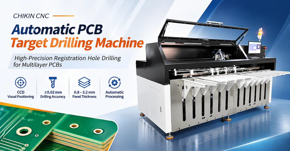
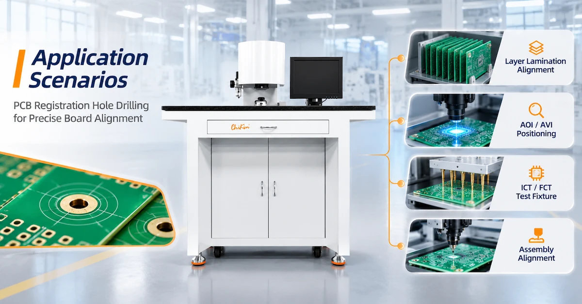
The company's PCB Registration Hole Drilling Machine is presented for producing locating holes used in alignment, tooling, and repeatable downstream processing.
Its published product description emphasizes a stable processing platform and consistent hole placement.
The visible machine arrangement includes an enclosed cabinet-style body, flat working surface, overhead processing structure, and operator controls.
However, the product page does not provide a complete numerical machine specification table.
Machine Evaluation Matrix
| Evaluation Item | Available Information | Buyer Confirmation Required |
|---|---|---|
| Primary application | PCB locating and registration holes | Exact production process |
| Machine structure | Cabinet-style workstation | Final configuration |
| Processing platform | Flat work surface | Usable dimensions |
| Processing head | Overhead unit visible | Actual drilling mechanism |
| Fixture arrangement | Fixture-style workholding visible | Compatible board sizes and fixtures |
| Control arrangement | Operator controls visible | Program and automation functions |
| Drilling accuracy | No complete numerical specification | Test method and tolerance |
| Hole diameter range | Not confirmed | Supported tooling |
| Material compatibility | Application-dependent | Qualified board types |
| Production throughput | Not confirmed | Actual cycle-time results |
Buyers should not transfer technical specifications from other CHIKIN models to this product without confirmation.
The final equipment proposal must identify the actual configuration and measurable acceptance criteria.
6. How to Perform a PCB Registration Hole First-Article Inspection
First-Article Inspection (FAI) verifies that an initial production sample conforms to the approved requirements before broader manufacturing begins.
For registration-hole processing, the inspection should include both dimensional measurement and actual fixture loading.
Step 1: Confirm the Approved Drawings
Verify that the PCB drawing and fixture drawing use the approved revisions.
Check hole dimensions, center coordinates, and measurement datums.
Step 2: Inspect the Workpiece Before Drilling
Confirm the PCB material, thickness, panel size, and relevant condition.
Record any existing bowing, damage, or unusual features.
Step 3: Prepare the Drilling Setup
Verify tooling, workpiece support, and the intended positioning method.
Use the approved machine procedure and record relevant setup conditions.
Step 4: Drill the Registration Holes
Process the sample panel according to the approved program.
Avoid altering several process parameters simultaneously during qualification.
Step 5: Measure the Finished Holes
Use suitable calibrated measuring equipment to inspect:
-
Hole diameter and geometry.
-
Hole center coordinates.
-
Center-to-center spacing.
-
Position relative to the defined datum.
-
Burrs and laminate condition.
Step 6: Test the Actual Mating Fixture
Place the completed board on the intended locating pins.
Check whether the board seats correctly without excessive force or unacceptable distortion.
Step 7: Repeat the Loading Operation
Remove and reload the board multiple times under controlled conditions.
Record any binding, seating variation, or positional movement.
Step 8: Approve or Reject the Sample
Compare the inspection results with the agreed acceptance criteria.
Document the decision and retain the relevant measurement records.
A first article should not be approved solely because the drilling machine completed its program without an alarm.
7. What Should a Fixture-Fit Inspection Report Include?
A useful inspection report should provide enough information to reproduce the test.
Recommended Inspection Record
| Record Field | Example Information |
|---|---|
| Workpiece identification | PCB part number and revision |
| Material | FR4 grade and construction |
| Panel dimensions | Length, width, and thickness |
| Registration-hole drawing | Approved coordinate reference |
| Fixture identification | Fixture number and revision |
| Locating pins | Dimensions and inspection status |
| Drilling equipment | Machine identification and setup |
| Hole measurements | Diameter and positional results |
| Fixture-fit result | Pass or fail against agreed criteria |
| Loading repeatability | Repeated installation observations |
| Surface condition | Burrs, cracks, or deformation |
| Final disposition | Accepted, rejected, or rework required |
For critical applications, measurement-system capability should also be assessed.
A measuring instrument must be sufficiently capable of distinguishing acceptable from unacceptable results at the required tolerance.
Where appropriate, the quality team may conduct a measurement-system analysis before relying on the inspection data.
8. Single-Pin vs Two-Pin Fixture Designs
Fixture design strongly influences registration performance.
A single locating pin can establish a reference position, but additional constraints are generally needed to control rotation.
Two locating features can establish both position and orientation when correctly designed.
However, an unsuitable two-pin arrangement can also create excessive constraint.
Fixture Design Comparison
| Arrangement | Main Function | Potential Limitation |
|---|---|---|
| Single round pin | Establishes a primary locating point | Does not independently control rotation |
| Two round pins | Establishes position and orientation | Can become over-constrained |
| Round and relieved locating pin | Controls location while allowing selected clearance | Requires appropriate engineering design |
| Edge stops with locating pin | Provides additional references | Depends on edge accuracy |
| Custom fixture | Matches application geometry | Requires validation and maintenance |
Some precision fixtures use a round locating pin together with a relieved or diamond-style locating feature to reduce binding caused by spacing variation.
This approach may be appropriate for certain designs, but its suitability must be determined by the responsible fixture engineer.
Why Should the Actual Fixture Be Included in FAT?
A dimensional inspection of drilled holes cannot fully reproduce the mechanical interaction during loading.
Using the intended fixture allows the buyer to evaluate actual installation behavior.
This is particularly valuable when the production process requires repeated positioning over many manufacturing cycles.
9. How to Test Repeat Loading and Registration Stability
A one-time successful fit does not demonstrate long-term process consistency.
Repeated loading tests can reveal problems associated with fixture wear, panel handling, or inconsistent seating.
Recommended Test Conditions
Use representative boards and the actual production fixture.
Define the number of loading cycles required by the quality plan.
Keep the inspection method consistent.
Record whether the board seats without excessive force and whether its final position remains within the agreed limit.
What Should Be Measured?
| Test | Purpose |
|---|---|
| Initial fixture fit | Establishes basic compatibility |
| Repeated loading | Evaluates positioning consistency |
| Multiple board samples | Checks sample-to-sample variation |
| Multiple material lots | Evaluates batch sensitivity |
| Different operators | Identifies handling variation |
| Fixture condition | Detects wear or contamination effects |
| Environmental conditions | Evaluates relevant dimensional changes |
A production qualification should include enough representative samples to provide meaningful evidence of the expected process variation.
The required sample size depends on the customer's quality system and the risk associated with the application.
10. Common Fixture-Fit Failures and Troubleshooting
When a board does not fit correctly, changing the drilling program immediately may not resolve the problem.
The cause may be associated with the fixture, inspection method, material, or handling procedure.
Troubleshooting Matrix
| Failure | Possible Cause | Recommended Action |
|---|---|---|
| Board binds on both pins | Incorrect hole spacing | Compare hole and fixture coordinates |
| One hole fits, second does not | Relative positional error | Measure center-to-center spacing |
| Different batches behave differently | Material variation | Compare lots and processing conditions |
| Board shifts after loading | Excessive clearance | Review pin and hole dimensions |
| Fit changes after cleaning | Debris or burr interference | Inspect contact surfaces |
| Repeated loading becomes difficult | Fixture wear or contamination | Inspect pins and seating surfaces |
| Inspection and fixture results disagree | Datum mismatch | Review the measurement reference |
| Board cracks during installation | Excessive force or inadequate support | Evaluate fixture and clearance |
Why Is Root-Cause Separation Important?
A hole-position error may resemble a fixture-position error.
Both can produce binding, but they require different corrective actions.
Engineers should measure the PCB and fixture independently before changing the machine setup.
For broader drilling accuracy diagnostics, refer to CHIKIN's PCB Hole Position Accuracy Guide.
11. How Does Fixture Fit Affect Production Cost?
Registration problems may generate costs outside the drilling workstation.
A board that fits poorly can require additional handling, manual adjustment, or rework during later manufacturing operations.
Main Cost Factors
| Cost Category | Potential Impact |
|---|---|
| Extra alignment time | Lower production efficiency |
| Repeated fixture adjustments | Increased setup labor |
| Rejected panels | Material waste |
| Additional inspection | Quality-control expense |
| Fixture rework | Tooling maintenance cost |
| Production interruptions | Reduced equipment availability |
| Downstream defects | Additional manufacturing losses |
A useful production metric is:
Registration Cost per Accepted Panel = Total Allocated Registration-Related Cost ÷ Accepted Panels
This includes costs directly attributable to the defined registration operation.
Why Is Accepted Output More Important Than Drilling Speed?
A machine may produce locating holes quickly but still generate poor downstream results if the board-to-fixture relationship is unstable.
For manufacturing efficiency, the real objective is the number of conforming panels that pass through the required production stages.
A complete cost evaluation should therefore consider drilling, inspection, fixture loading, and any associated rework.
12. How to Evaluate the Machine During Factory Acceptance Testing
A Factory Acceptance Test (FAT) helps establish whether the proposed equipment satisfies the agreed application requirements before delivery.
For PCB registration-hole drilling, FAT should include physical fixture-fit validation.
Recommended FAT Checklist
| Acceptance Item | Required Verification |
|---|---|
| Machine configuration | Confirm the actual drilling system |
| PCB material | Test representative production boards |
| Board dimensions | Verify required handling and processing area |
| Hole diameter | Measure completed holes |
| Hole coordinates | Verify the approved datums |
| Hole spacing | Measure center-to-center relationships |
| Workholding | Confirm stable board support |
| Fixture compatibility | Test the intended downstream fixture |
| Repeat loading | Assess positioning consistency |
| Surface integrity | Inspect burrs and laminate damage |
| Production cycle | Measure complete operating time |
| Operator controls | Verify required functions |
| Safety systems | Review guards and emergency controls |
| Documentation | Obtain inspection and operating records |
Recommended FAT Procedure
First, provide the approved PCB and fixture drawings.
Second, establish the required hole specifications and acceptance limits.
Third, process representative panels using the proposed machine.
Fourth, inspect completed holes using appropriate calibrated equipment.
Fifth, install the boards into the actual downstream fixture.
Sixth, perform repeated loading tests and record the results.
Finally, document accepted and rejected samples, machine settings, and any required corrective actions.
The acceptance agreement should define what constitutes a successful test before equipment shipment.
13. What Should PCB Buyers Include in an RFQ?
A complete request for quotation helps the supplier understand the manufacturing application.
Rather than asking only for a PCB registration hole drilling machine price, buyers should provide the technical requirements that determine compatibility.
PCB Registration Hole Drilling RFQ Checklist
| Required Information | Buyer Should Provide |
|---|---|
| PCB material | FR4, multilayer, or other construction |
| Panel dimensions | Minimum and maximum sizes |
| Material thickness | Actual production range |
| Registration holes | Diameter, quantity, and coordinates |
| Datum system | Approved mechanical reference |
| Hole tolerance | Size and positional limits |
| Fixture details | Pin dimensions, spacing, and drawings |
| Required fit | Loading clearance and repeatability criteria |
| Current problems | Binding, movement, or rework |
| Production volume | Panels per hour or shift |
| Inspection | Measuring method and acceptance limits |
| Automation | Required handling or control functions |
| Factory utilities | Electrical and pneumatic requirements |
| Commercial terms | Delivery, warranty, and support requirements |
Why Discuss Fixture Fit with CHIKIN CNC?
CHIKIN CNC supplies PCB drilling, routing, and related processing equipment for industrial manufacturers.
Its PCB Registration Hole Drilling Machine is positioned for creating locating holes that support repeatable board alignment.
Because the publicly available product description does not establish all relevant machine specifications, buyers should request confirmation of processing area, drilling mechanism, workholding, supported hole sizes, accuracy, and operating functions.
Request a Technical Evaluation
For an application-specific equipment review, provide the PCB drawing, mating-fixture drawing, material specifications, positional tolerances, and expected production output.
Contact CHIKIN CNC for a PCB Registration Hole Drilling Machine Technical Review and Quotation.
A complete application brief allows the supplier to evaluate the equipment against the actual downstream fixture requirements.
14. Frequently Asked Questions About PCB Registration Hole Fixture Fit
1. What is a PCB registration hole drilling machine?
It is equipment used to create locating or registration holes in suitable PCB materials. These holes can provide mechanical references for tooling, alignment, and downstream manufacturing operations.
2. Why can a PCB with accurate holes fail to fit a fixture?
Fixture compatibility depends on hole positions, hole diameters, pin dimensions, spacing, and board condition. A hole may meet its individual size tolerance while the complete hole pattern does not match the mating fixture.
3. How is registration-hole clearance calculated?
Basic diametral clearance is the hole diameter minus the locating-pin diameter. Actual fixture fit must also account for positional differences and the complete locating arrangement.
4. Is a tighter hole tolerance always better?
Not necessarily. The required tolerance should match the intended fixture function, manufacturing capability, and positioning requirements. Excessively restrictive dimensions can increase cost without providing a useful process benefit.
5. Can CCD positioning eliminate fixture-fit problems?
CCD alignment can support detection of actual reference positions when included in the machine configuration. However, it cannot automatically correct every hole-size, fixture-spacing, material-deformation, or workholding problem.
6. What is the most important first-article inspection?
The inspection should verify that the completed hole geometry meets the drawing and that the board fits the intended downstream fixture under the agreed loading conditions.
7. How should registration-hole repeatability be tested?
Process multiple representative boards, measure the required hole relationships, and perform repeated loading trials using the actual fixture. Record results using consistent datums and measurement methods.
8. Can FR4 dimensional changes affect fixture fit?
Yes. Changes in material condition, temperature, manufacturing history, or handling can affect board dimensions. Qualification should reflect the actual production stage and relevant environmental conditions.
9. What information should be included in a Factory Acceptance Test?
Include the machine configuration, board material, hole specifications, approved datums, dimensional measurements, mating-fixture trials, repeated loading results, safety checks, and documented acceptance criteria.
10. How can overseas buyers request a suitable machine from CHIKIN CNC?
Provide the PCB drawings, material type, panel dimensions, registration-hole requirements, fixture-pin dimensions, production volume, and quality expectations. Request confirmation of equipment compatibility and a representative sample test.
Conclusion
Successful PCB registration hole fixture fit requires more than producing holes at nominal coordinates.
For PCB manufacturers, the critical requirement is ensuring that completed boards can be positioned consistently in the intended downstream fixture without excessive force, unacceptable movement, or repeated manual correction.
A reliable qualification process should evaluate hole geometry, datum relationships, pin clearance, laminate condition, dimensional repeatability, and actual fixture-loading performance.
The most effective equipment selection approach combines accurate engineering drawings, representative board samples, calibrated inspection, and a documented Factory Acceptance Test.
CHIKIN CNC provides PCB manufacturing equipment for companies evaluating more controlled registration-hole processing and repeatable board positioning.
To determine whether the proposed configuration matches your production requirements, provide your PCB drawings, fixture specifications, required tolerances, and target output.
Contact CHIKIN CNC for a Technical Evaluation and Quotation to discuss your PCB registration-hole drilling application and the acceptance criteria needed for reliable downstream fixture compatibility.