



Quick Answer: What Is the CK-T1 PCB Target Driller?
A PCB target driller is specialized equipment used to create accurately positioned registration or tooling holes in suitable printed circuit boards. A vision-assisted system helps operators identify reference targets and align drilling operations with the actual panel position.
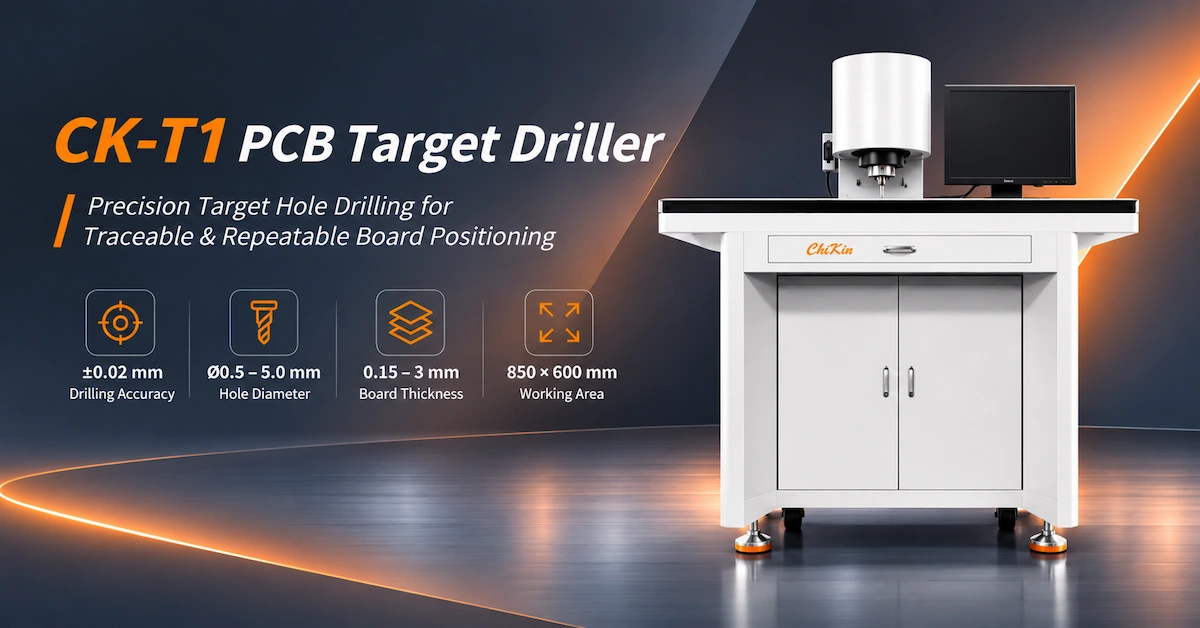
The CHIKIN CNC CK-T1 is a compact target drilling machine featuring a 40,000 RPM spindle, 300W spindle power, a visual positioning system, and a published processing area of 500 × 800 mm. Its specified drilling accuracy is ±0.02 mm, with a hole-diameter deviation of ≤0.03 mm.
For PCB manufacturers, the main purchasing priorities are target recognition, hole-position accuracy, compatible materials, repeatable production, and verified drilling quality.
Key Takeaways
-
Compact drilling workstation: The CK-T1 has published machine dimensions of 920 × 770 × 1200 mm.
-
Visual positioning: An included vision system and high-power LED light source support evaluation of target recognition.
-
Precision drilling: Published drilling accuracy is ±0.02 mm, with a maximum hole-diameter deviation of 0.03 mm.
-
Tool capability: The specification lists Ø0.5–5.0 mm drilling diameters and a 40,000 RPM spindle.
-
Material range: Listed applications include single- and double-sided substrates, copper-based boards, aluminum-based boards, and other metal substrates.
-
Production efficiency: The rated drilling speed is 40–60 holes/min, but actual panel throughput requires testing.
The best purchasing decision should be based on sample drilling and documented acceptance criteria rather than nominal specifications alone.
1. What Is a PCB Target Driller Used For?
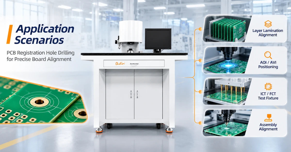
A PCB target driller creates holes at defined reference positions on printed circuit boards or related manufacturing substrates.
These holes may be used for tooling, registration, fixture positioning, or subsequent manufacturing operations.
In multilayer PCB manufacturing, controlling the relationship between target features and drilled reference holes can be important for maintaining process consistency.
Why Are Registration Holes Important?
PCB production involves several operations where accurate panel positioning is necessary.
When a panel is incorrectly aligned, later processing can introduce additional positional errors.
A target drilling operation can help establish defined mechanical references.
Typical applications include:
-
PCB registration-hole preparation.
-
Target-hole drilling.
-
Tooling and guide-hole processing.
-
Positioning of suitable rigid PCB panels.
-
Preparation for compatible downstream fixtures.
-
Reference-hole processing for selected multilayer manufacturing workflows.
Target Drilling vs Conventional PCB Drilling
| Evaluation | PCB Target Drilling | Conventional PCB Drilling |
|---|---|---|
| Primary purpose | Registration and reference holes | Functional and mechanical holes |
| Positioning method | Vision-assisted references where provided | Programmed drilling coordinates |
| Typical hole quantity | Application-dependent reference pattern | Often larger production hole patterns |
| Main quality concern | Reference-hole location | Hole geometry, location and throughput |
| Common buyer | PCB process engineer | PCB drilling production manager |
A PCB target driller should not be selected as a substitute for a high-volume micro-drilling machine without confirming its actual capabilities.
2. CHIKIN CNC CK-T1 Technical Specifications
The CHIKIN CNC PCB Target Driller is presented as an industrial workstation for controlled target drilling and PCB positioning applications.
The supplied product information identifies the following technical specifications.
CK-T1 Machine Specification Table
| Technical Parameter | Published Specification |
|---|---|
| Machine model | CK-T1 |
| Equipment category | PCB Target Driller |
| NC system | CHIKIN CNC |
| Spindle speed | 40,000 RPM |
| Spindle power | 300W |
| Z-axis control | Cylinder transmission |
| Drilling-hole diameter | Ø0.5–5.0 mm |
| Visual system | Included |
| Processing area | 500 × 800 mm |
| Processing thickness | 0.5–5.0 mm |
| Drilling accuracy | ±0.02 mm |
| Hole-diameter deviation | ≤0.03 mm |
| Drilling speed | 40–60 holes/min |
| Light source | High-power LED |
| Air supply | Dry air, ≥0.5 MPa |
| Power supply | Single-phase AC220V ±10% |
| Maximum power consumption | 1.5kVA |
| Machine dimensions | 920 × 770 × 1200 mm |
| Machine weight | Approximately 280 kg |
Specifications are based on the supplied CK-T1 product datasheet. Actual drilling performance, tooling compatibility, and finished-hole quality require confirmation under defined production conditions.
Which Specifications Should Buyers Verify?
Three areas deserve particular attention.
Processing area: The listed 500 × 800 mm dimensions should be checked against the actual usable drilling envelope, including fixture clearances and target positions.
Drilling accuracy: The published ±0.02 mm specification requires confirmation of the measurement method, material conditions, and position reference.
Drilling efficiency: The quoted 40–60 holes/min does not automatically include loading, alignment, inspection, or unloading.
These details should be included in the final technical agreement.
3. How Does Visual Target Recognition Support Drilling Accuracy?
The CK-T1 specification includes a visual system and high-power LED illumination.
Vision-assisted positioning helps determine where the actual target features are located before processing.
A typical workflow involves capturing the target image, identifying its reference position, and aligning the drilling operation accordingly.
Why Does the Light Source Matter?
Target recognition depends on image quality.
Different PCB surfaces may reflect light differently, especially when the target is surrounded by copper, solder mask, or other surface features.
Lighting conditions can influence the visibility of target boundaries.
Key Vision-System Evaluation Factors
| Factor | What Buyers Should Verify |
|---|---|
| Target shape | Supported recognition patterns |
| Target dimensions | Minimum and maximum recognized features |
| Surface contrast | Detection on actual production materials |
| LED illumination | Adjustable lighting functions |
| Camera resolution | Ability to identify the required target |
| Recognition repeatability | Results across repeated measurements |
| Alignment method | How the machine applies corrections |
| Failed recognition | Alarm and operator response |
Does the CK-T1 Automatically Recognize Every Target?
No universal recognition capability should be assumed.
The supplied datasheet confirms that a visual system is included, but it does not identify the exact recognition algorithms, camera specifications, or supported target patterns.
Buyers should provide real panel samples and request a demonstration using the actual production targets.
The relevant result is not simply whether the camera detects a target, but whether the completed hole meets its required position tolerance.
4. How Should Buyers Interpret ±0.02 mm Drilling Accuracy?
The CK-T1 lists ±0.02 mm drilling accuracy and ≤0.03 mm hole-diameter deviation.
These specifications describe different characteristics.
Drilling Accuracy vs Hole-Diameter Deviation
| Parameter | Meaning | Recommended Measurement |
|---|---|---|
| Drilling position accuracy | Location of the completed hole relative to the specified reference | Optical or coordinate measurement |
| Hole-diameter deviation | Difference between actual and specified hole diameter | Calibrated dimensional measurement |
| Repeatability | Variation between repeated operations | Multi-sample inspection |
| Target-recognition accuracy | Accuracy of detecting a visual reference | Vision calibration and reference test |
| Finished-board registration | Alignment achieved across subsequent manufacturing processes | Process-specific inspection |
The datasheet does not separately quantify every one of these measurements.
Therefore, the quoted drilling accuracy should not be treated as a guarantee of complete multilayer registration performance.
What Causes Actual Hole-Position Variation?
Several factors may contribute:
-
Target recognition errors.
-
Panel movement during drilling.
-
Incorrect coordinate calibration.
-
Drill-bit runout.
-
Tool deflection.
-
Inadequate board support.
-
Material variation.
-
Measurement-datum differences.
For a detailed explanation of these factors, see the CHIKIN PCB Hole Position Accuracy Guide.
How Should Accuracy Be Verified?
Use representative production panels with actual target features.
Define the hole-center position, tolerance, and reference datum before testing.
Process multiple boards and inspect the completed holes using suitable calibrated equipment.
Testing should cover the required processing area, not only a single convenient position.
5. Which PCB Materials Can the CK-T1 Process?
The CK-T1 is listed for common single- and double-sided substrates, copper-based substrates, aluminum-based substrates, and other metal substrates.
However, these materials have different cutting characteristics.
Material Compatibility Matrix
| PCB Material | Application Consideration | Main Risk |
|---|---|---|
| Single-sided PCB | Tooling and registration holes | Edge burrs and dimensional accuracy |
| Double-sided PCB | Reference-hole processing | Copper damage near holes |
| FR4 rigid PCB | Suitable registration drilling | Glass-fiber wear and hole quality |
| Copper-based substrate | Material-specific tooling | Cutting load and burr formation |
| Aluminum-based substrate | Selected reference-hole applications | Metal burrs and chip evacuation |
| Other metal-core boards | Qualified drilling applications | Material and tool compatibility |
FR4 and multilayer constructions should be validated for the actual application rather than assumed to perform identically to the substrates listed in the datasheet.
What Does the 0.5–5.0 mm Thickness Range Mean?
The CK-T1 specifies a processing thickness range of 0.5–5.0 mm.
Actual performance within that range depends on material construction, drill geometry, cutting parameters, and fixture support.
A 5 mm thick metal-based substrate may present different cutting requirements from a 5 mm rigid composite board.
The correct drilling configuration should therefore be verified using material samples.
Can One Drill Bit Process Every Material?
Not necessarily.
FR4 contains abrasive glass reinforcement, while aluminum and copper can present different chip-formation and cutting-load conditions.
Tool selection should follow the material and drilling-tool manufacturer's approved recommendations.
6. How Do the 40,000 RPM Spindle and Cylinder Z-Axis Affect Processing?
The CK-T1 lists a 40,000 RPM spindle with 300W rated power and cylinder-based Z-axis control.
These are important machine configuration details.
Why Does Spindle Speed Matter?
Spindle speed influences the interaction between the drill and workpiece.
However, the best speed depends on material, drill diameter, feed rate, and cutting depth.
A higher spindle speed does not automatically produce better hole quality.
What Does Cylinder-Based Z-Axis Control Mean?
A cylinder transmission uses an actuator arrangement to generate vertical movement.
Its actual motion behavior depends on the machine's pneumatic and control system.
Buyers should confirm the drilling-depth adjustment method, movement control, available travel, and suitability for the intended hole requirements.
Spindle and Motion Checklist
| Equipment Feature | Buyer Question |
|---|---|
| 40,000 RPM spindle | Which drill sizes and materials are approved? |
| 300W spindle power | Is the configuration suitable for the application? |
| Cylinder Z-axis | How is drilling depth controlled? |
| Spindle collet | Which tool shanks are compatible? |
| Tool replacement | How are tools installed and checked? |
| Feed control | Which operating parameters are adjustable? |
| Calibration | How is drilling position verified? |
The CK-T1 should be evaluated according to its own specifications.
The higher spindle power or different motion arrangements listed on other CHIKIN target drilling models must not be assumed to apply to the CK-T1.
7. What Does 40–60 Holes per Minute Mean for Production?
The CK-T1 datasheet lists a drilling speed of 40–60 holes/min.
This provides a preliminary reference for the drilling operation.
However, total panel throughput depends on more than the hole-processing rate.
Main Production Factors
| Factor | Impact |
|---|---|
| Holes per panel | Determines drilling operations |
| Target recognition | Adds alignment time |
| Workpiece positioning | Influences cycle stability |
| Panel loading | Requires operator or handling time |
| Drilling depth | Affects qualified cutting conditions |
| Tool changes | Can interrupt production |
| Quality inspection | Adds verification time |
A complete production cycle should be measured as:
Total Cycle Time = Loading + Target Recognition + Positioning + Drilling + Inspection + Unloading
How Should Buyers Estimate Actual Output?
Use the intended PCB panel and hole pattern.
Measure the time required to process a complete panel, including the necessary handling and inspection stages.
Then calculate:
Accepted Panels per Hour = Completed Panels per Hour × Acceptance Rate
A faster nominal drilling rate is not economically useful if it produces unacceptable hole-position variation or additional rework.
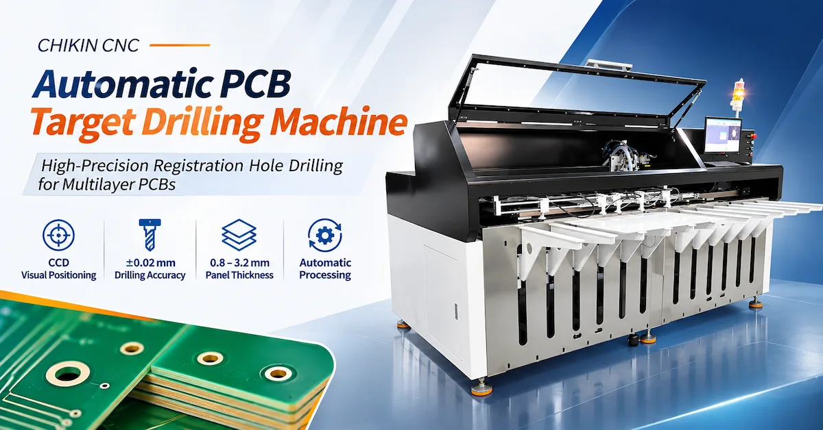
8. CK-T1 vs Larger Automatic PCB Target Drilling Machines
Different PCB factories require different levels of equipment capacity and automation.
The CK-T1 is a compact target drilling workstation.
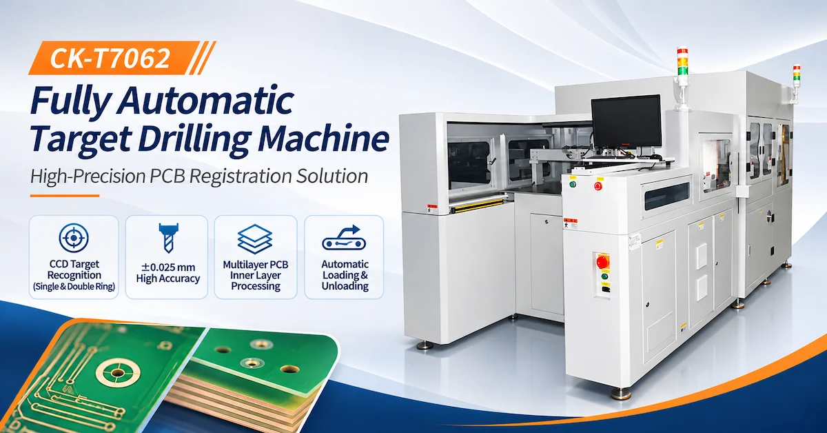
CHIKIN CNC also supplies larger target drilling equipment and automated configurations.
Equipment Selection Comparison
| Evaluation | CK-T1 PCB Target Driller | Larger Automatic Target Drilling Platform |
|---|---|---|
| Main purpose | Controlled target-hole processing | Target drilling with configuration-dependent automation |
| Workstation size | Compact published machine dimensions | Generally larger machine footprint |
| Visual positioning | Included vision system | Depends on model; CCD configurations available |
| Loading | Confirm actual operating method | Automatic handling available on specified models |
| Production capacity | Verify full panel cycle | Verify full automated cycle |
| Installation | Lower published power demand than some larger models | Additional utility and integration requirements may apply |
| Main purchasing priority | Hole quality and suitable panel handling | Integration, throughput and quality |
For example, the CHIKIN CK-T7062 Fully Automatic Target Drilling Machine lists CCD target recognition and automatic loading and unloading.
The correct choice depends on panel dimensions, required processing, automation needs, available floor space, and actual production output.
When Is the CK-T1 Worth Considering?
It is particularly relevant when the factory needs a dedicated target drilling station and the required panels fit within its approved processing envelope.
For high-volume production requiring automatic material transfer, a larger integrated system may deserve evaluation.
9. How Does the CK-T1 Fit Into a PCB Manufacturing Workflow?
A target drilling station should be integrated according to the actual manufacturing process.
The following is a recommended evaluation workflow; it does not replace the machine manufacturer's operating instructions.
Step 1: Prepare the PCB Panel
Confirm the material, dimensions, thickness, and target positions.
Step 2: Position the Workpiece
Load and support the board using the approved fixture arrangement.
Step 3: Identify the Targets
Use the visual system to locate the required reference features.
Step 4: Confirm Alignment
Verify that the machine has established the correct drilling references.
Step 5: Perform Drilling
Process the required holes using the qualified tool and operating settings.
Step 6: Inspect the Results
Measure the completed hole positions and diameters.
Step 7: Record Production Results
Retain inspection records and relevant process information according to the factory's quality requirements.
What Does Traceable Board Positioning Mean?
Traceability in manufacturing requires records that connect processing results to the correct workpiece or production batch.
The CK-T1 product title mentions traceable positioning, but the supplied technical specification does not confirm automatic serial-number marking, QR-code generation, database integration, or MES connectivity.
These should be treated as separate functions requiring confirmation.
A target drilling machine creates physical reference holes; it does not automatically provide a complete product-traceability system.
10. Common PCB Target Drilling Problems and Solutions
Different problems require different corrective actions.
Troubleshooting Table
| Problem | Possible Cause | First Check |
|---|---|---|
| Target recognition failure | Poor lighting or insufficient contrast | Camera image and target condition |
| Hole-position error | Alignment or fixture movement | Workpiece and datum verification |
| Oversized holes | Tool runout or unsuitable drill | Tool and spindle inspection |
| Hole burrs | Incorrect cutting conditions | Tool geometry and material |
| Incomplete drilling | Incorrect depth or setup | Z-axis configuration |
| Inconsistent batches | Calibration or setup variation | Repeatability testing |
| Tool damage | Excessive loading or handling | Tool condition and parameters |
| Slow production | Handling or inspection bottleneck | Complete cycle-time measurement |
Why Should Process Engineers Separate Vision and Drilling Errors?
If the vision system detects the correct target but the finished hole is displaced, the cause may lie in machine movement, clamping, or tool behavior.
If the target itself is recognized incorrectly, adjusting drilling parameters will not resolve the underlying problem.
A structured troubleshooting process should examine the complete sequence.
11. CK-T1 Factory Acceptance Test: What Should Buyers Verify?
A Factory Acceptance Test (FAT) helps establish whether the supplied machine meets the required manufacturing conditions.
For the CK-T1, testing should focus on vision recognition, finished-hole quality, and repeatability.
CK-T1 FAT Checklist
| Test Item | Recommended Verification |
|---|---|
| Machine model | Confirm CK-T1 |
| Processing area | Verify required positions within 500 × 800 mm |
| Material thickness | Test the relevant 0.5–5.0 mm range |
| Drilling diameter | Measure the required Ø0.5–5.0 mm holes |
| Vision system | Demonstrate recognition on actual targets |
| LED illumination | Confirm appropriate target visibility |
| Drilling accuracy | Verify the specified ±0.02 mm criterion |
| Hole diameter | Check the ≤0.03 mm deviation criterion |
| Spindle operation | Confirm the quoted 40,000 RPM configuration |
| Z-axis operation | Demonstrate required drilling-depth control |
| Production speed | Measure qualified hole-processing time |
| Repeatability | Compare multiple boards |
| Safety | Verify guarding and emergency functions |
| Documentation | Review operation, maintenance and inspection records |
Recommended Sample Validation Procedure
First, provide actual PCB samples representing the intended board materials and dimensions.
Second, define target geometry, hole locations, and permitted tolerances.
Third, establish the agreed drilling and alignment procedure.
Fourth, process multiple samples under controlled conditions.
Fifth, inspect the finished holes using calibrated measurement equipment.
Finally, record recognition failures, dimensional results, tool condition, and complete cycle times.
This produces a stronger purchasing basis than relying only on advertised accuracy.
12. Installation and Maintenance Considerations
The CK-T1 is a compact floor-standing industrial machine.
Before purchasing, factories should confirm electrical, pneumatic, installation, and operator requirements.
Published Installation Specifications
| Requirement | CK-T1 Specification |
|---|---|
| Electrical supply | Single-phase AC220V ±10% |
| Maximum power consumption | 1.5kVA |
| Compressed air | Dry air ≥0.5MPa |
| Machine dimensions | 920 × 770 × 1200 mm |
| Machine weight | Approximately 280kg |
What Maintenance Should Buyers Plan?
Relevant inspection activities may include:
-
Checking drill-bit condition.
-
Inspecting spindle-tool holding.
-
Cleaning camera and illumination surfaces.
-
Verifying machine positioning.
-
Checking pneumatic connections.
-
Inspecting workpiece support.
-
Reviewing safety controls.
The exact maintenance schedule should follow the delivered machine's technical documentation.
Safety Considerations
Industrial drilling equipment presents hazards involving rotating tools, moving actuators, and workpiece handling.
Buyers should verify guards, emergency-stop performance, electrical protection, and safe maintenance procedures.
Applicable machinery safety references may include ISO 12100 and IEC 60204-1, depending on the destination market and delivered configuration.
The product's appearance alone does not establish certification or compliance.
13. PCB Target Driller RFQ Checklist for Overseas Buyers
A detailed request for quotation helps the supplier determine whether the CK-T1 can meet the customer's requirements.
Technical RFQ Checklist
| Required Information | Buyer Should Provide |
|---|---|
| PCB material | FR4, copper-based, aluminum-based, or other |
| Board dimensions | Minimum and maximum sizes |
| Material thickness | Actual production range |
| Target geometry | Shape, dimensions, and appearance |
| Hole diameter | Required size and tolerance |
| Hole coordinates | Drawing and reference datums |
| Drilling accuracy | Required finished-hole tolerance |
| Production volume | Panels and holes per shift |
| Vision requirements | Actual target samples |
| Tooling | Preferred drill dimensions and material |
| Workpiece handling | Manual or required automation |
| Quality inspection | Sample and FAT acceptance criteria |
| Factory utilities | Electrical and compressed-air supply |
| Commercial requirements | Quantity, delivery destination and support needs |
Why Consider CHIKIN CNC?
CHIKIN CNC, operated by Shenzhen ChiKin Automation Equipment Co., Ltd., supplies PCB drilling, routing, target drilling, and related manufacturing equipment.
The CK-T1 offers a compact target-drilling configuration for factories evaluating controlled registration-hole processing.
For buyers, the most valuable supplier discussion should focus on application compatibility, sample drilling, quality inspection, and the final machine configuration.
Request a CK-T1 Technical Evaluation
If your factory needs accurate PCB target-hole processing, prepare your panel drawings, target specifications, required tolerances, and production volume.
Review the CHIKIN CK-T1 PCB Target Driller.
Contact CHIKIN CNC to Request a CK-T1 Technical Review and Quotation.
Providing actual production samples and a complete technical specification will help establish whether the CK-T1 meets your manufacturing requirements.
14. Frequently Asked Questions About PCB Target Drillers
1. What is a PCB target driller?
A PCB target driller is equipment used to produce accurately positioned reference or tooling holes in suitable PCB materials. Vision-assisted systems can locate designated target features before drilling.
2. What is the processing area of the CK-T1?
The published specification lists 500 × 800 mm. Buyers should verify the actual usable drilling envelope, fixture clearance, and panel orientation.
3. What drilling accuracy does the CK-T1 offer?
The datasheet lists ±0.02 mm drilling accuracy and hole-diameter deviation of ≤0.03 mm. Actual results should be verified through sample drilling and calibrated measurements.
4. What hole diameters can the CK-T1 drill?
The published range is Ø0.5–5.0 mm. Tooling compatibility and material-specific drilling performance should be confirmed.
5. Does the CK-T1 include a vision system?
Yes. The specification identifies an included visual system and high-power LED illumination. Exact recognition functions and camera specifications require confirmation.
6. What is the spindle speed of the CK-T1?
The machine lists a 40,000 RPM spindle with 300W rated power. Approved speed and feed settings depend on material and drill diameter.
7. Can the CK-T1 process aluminum-based PCB materials?
Aluminum-based substrates are included in its listed application materials. Actual compatibility requires appropriate tooling and sample testing.
8. Does 40–60 holes/min mean 60 completed panels per minute?
No. The figure refers to drilling operations. Complete panel throughput also depends on hole count, alignment, handling, inspection, and other processing stages.
9. Does the CK-T1 automatically generate traceability codes?
The supplied specification does not confirm QR-code generation, serial-number marking, or MES connectivity. These functions should be verified separately if required.
10. How can overseas buyers request a CK-T1 quotation?
Provide PCB material, panel size, thickness, target geometry, hole dimensions, required accuracy, production volume, and factory utilities. Request sample processing and defined acceptance criteria before finalizing an equipment order.
Conclusion
Selecting the right PCB target driller requires careful evaluation of visual positioning, hole accuracy, material compatibility, drilling performance, and production workflow.
The CHIKIN CNC CK-T1 provides a compact industrial configuration featuring a 500 × 800 mm processing area, 40,000 RPM spindle, included visual system, ±0.02 mm published drilling accuracy, and 40–60 holes/min rated drilling speed.
These specifications make it a relevant candidate for PCB manufacturers evaluating controlled reference-hole processing and repeatable panel positioning.
However, equipment selection should not rely solely on nominal accuracy or speed figures.
Buyers should test the machine using actual PCB materials, target patterns, hole locations, and acceptance requirements. A documented factory acceptance procedure can help confirm processing quality and identify practical limitations before purchase.
For overseas B2B manufacturers, the most valuable investment is the equipment configuration that produces consistently acceptable holes while fitting the factory's real production and operating requirements.
Explore the CHIKIN CNC PCB Target Driller or contact CHIKIN CNC for an application-specific technical evaluation and quotation.
Share your PCB drawings, target information, material specifications, required drilling tolerance, and production targets to evaluate whether the CK-T1 is suitable for your PCB registration workflow.