



TL;DR — Quick Answer
A CCD film punching machine uses a vision-assisted positioning system and mechanical punching tooling to produce holes in compatible thin-film materials. It is particularly relevant to manufacturers that require repeatable registration holes, alignment features, or accurately positioned openings in flexible sheet materials.
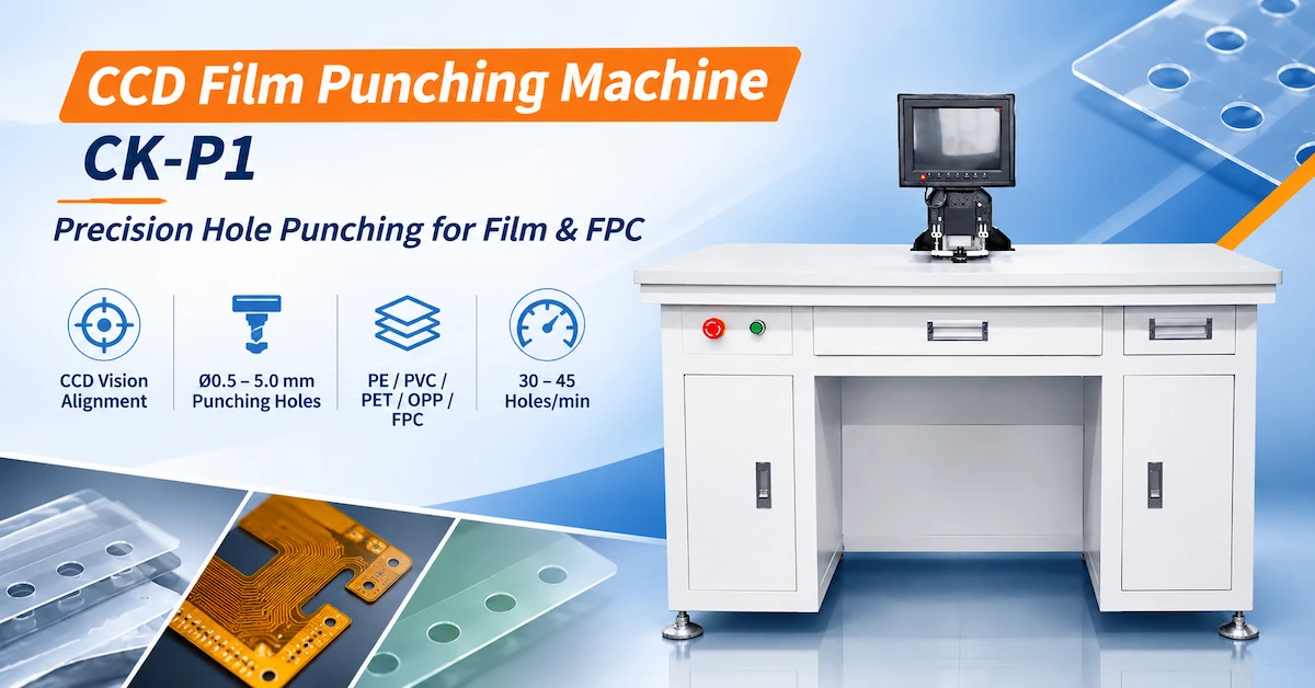
The CHIKIN CNC CK-P1 is a film punching machine with a published 530 × 1000 mm processing panel size, Ø0.5–5.0 mm punching-hole range, ±0.015 mm processing accuracy, and 30–45 holes/min rated punching speed.
Its listed applications include PE, PVC, PET, OPP films, flexible circuit boards, and other suitable specialty films. Actual material compatibility, finished-hole accuracy, and production output should be verified using representative samples.
For industrial buyers, the right purchasing decision depends on vision positioning, tooling quality, material protection, dimensional consistency, and accepted production throughput.
Key Takeaways
-
Precision punching: The CK-P1 lists an adjustable or customizable punching-hole diameter range of Ø0.5–5.0 mm.
-
CCD vision system: A visual positioning system is included, supporting evaluation of vision-assisted hole registration.
-
Material compatibility: The datasheet lists general film thickness of 0.05–0.2 mm and a separate PET thickness range of 0.05–0.8 mm.
-
Published accuracy: ±0.015 mm processing accuracy is specified, but actual finished-hole tolerances require testing.
-
Production speed: The machine lists 30–45 holes/min, which should be verified against actual production layouts.
-
Buyer priority: Punching accuracy, die condition, film handling, material deformation, and inspection results are more important than nominal punching speed alone.
1. What Is a CCD Film Punching Machine?
A CCD film punching machine is a precision manufacturing system that combines visual positioning with mechanical hole punching.
In a typical process, the workpiece is positioned, a vision system identifies reference features, and the punching mechanism creates holes according to the required geometry.
The objective is to reduce positional variation during repetitive processing of suitable thin-film materials.
What Is the Difference Between Film Punching and Conventional PCB Drilling?
These processes use different methods to remove material.
Film punching creates holes using a mechanical punch and die arrangement.
PCB drilling generally uses a rotating cutting tool to remove material from rigid or compatible flexible circuit constructions.
For thin-film applications, punching may offer advantages when repeated holes have consistent dimensions and the tooling has been qualified for the material.
However, punching tools require correct die clearance, accurate alignment, and suitable material support.
Typical Applications
CCD film punching equipment may be evaluated for:
-
Registration holes in flexible circuit materials.
-
Positioning holes in PET and other plastic films.
-
Guide-hole preparation for downstream processing.
-
Repetitive openings in suitable industrial films.
-
Flexible electronic material preparation.
-
Thin-film production requiring accurate hole placement.
Not every material or hole geometry is suitable for punching.
The appropriate process should be determined from the material stack, thickness, hole dimensions, and required finished-part quality.
2. CCD Film Punching vs Mechanical Drilling vs Laser Cutting
Manufacturers processing flexible materials often compare punching, mechanical drilling, and laser cutting.
Each technology has different strengths and limitations.
Process Comparison
| Evaluation Factor | CCD Film Punching | Mechanical Drilling | Laser Cutting |
|---|---|---|---|
| Material removal | Punch and die | Rotating cutting tool | Focused laser energy |
| Tool contact | Mechanical contact | Mechanical contact | Non-contact beam |
| Repeated identical holes | Suitable when qualified | Suitable when qualified | Suitable when qualified |
| Tool wear | Punch and die wear | Drill wear | No conventional cutting-bit wear |
| Mechanical force | Punching force | Drilling force | Low direct mechanical loading |
| Thermal influence | No laser-induced heat-affected zone | Cutting heat may occur | Thermal effects require evaluation |
| Hole geometry | Defined by tooling | Defined by drill geometry | Defined by laser processing |
| Design changes | May require tooling changes | Program and tool changes | Program changes |
| Main purchasing concern | Tooling, registration, material deformation | Drill accuracy and burrs | Heat effects and cutting quality |
When Is CCD Film Punching a Good Choice?
It is worth evaluating when the manufacturing requirement involves repeated holes of established dimensions and the selected material responds well to mechanical punching.
The process may also be useful when vision-assisted positioning can reduce the need for repeated manual alignment.
When Is Laser Processing More Appropriate?
Laser processing may be preferable for extremely delicate materials, intricate contours, or designs that would otherwise require complicated mechanical tooling.
For suitable flexible electronic applications, manufacturers can compare the CK-P1 with CHIKIN CNC laser cutting equipment.
The correct choice should be based on finished-hole quality, material compatibility, tooling requirements, and actual production cost.
3. CHIKIN CNC CK-P1 Technical Specifications
CHIKIN CNC, operated by Shenzhen ChiKin Automation Equipment Co., Ltd., supplies PCB manufacturing and related precision processing equipment.
The CK-P1 is presented as a vision-equipped film punching system for compatible industrial sheet materials.
CK-P1 Machine Specification Table
| Technical Parameter | Published Specification |
|---|---|
| Model | CK-P1 |
| Equipment type | CCD film punching machine |
| NC system | CHIKIN |
| Film processing thickness | 0.05–0.2 mm |
| PET processing thickness | 0.05–0.8 mm |
| Visual system | Included |
| Identifiable hole diameter | Ø0.5–5.0 mm, customizable |
| Punching-hole diameter | Ø0.5–5.0 mm, customizable |
| Air pressure | 0.5 MPa |
| Processing panel size | 530 × 1000 mm |
| Processing accuracy | ±0.015 mm |
| Punching speed | 30–45 holes/min |
| Machine dimensions | 1200 × 760 × 1100 mm |
| Machine power | 1 kW |
| Power supply | AC220V / 50Hz |
| Machine weight | Approximately 260 kg |
| Listed materials | PE, PVC, PET, OPP films, flexible circuit boards and specialty films |
The figures above are supplier-published specifications. Finished-part accuracy, suitable punching conditions, and material compatibility must be confirmed through machine-specific testing.
Which Specifications Require Further Confirmation?
Several figures are important enough to verify before purchase.
Processing accuracy: The datasheet lists ±0.015 mm but does not specify the measurement method, positional reference, or full working-area test conditions.
Material thickness: PET has a separately listed range. The buyer should verify the supported thickness range for PE, PVC, OPP, and complete flexible circuit constructions.
Customizable hole diameter: The datasheet states that Ø0.5–5.0 mm hole specifications can be customized, but availability of alternative dimensions requires supplier confirmation.
Punching speed: The listed 30–45 holes/min does not automatically include loading, alignment, inspection, or unloading.
These details should be included in the final equipment acceptance agreement.
4. Why Does CCD Vision Alignment Matter in Film Punching?
Thin films may shift, stretch, or change position during loading and handling.
If the machine depends entirely on an assumed workpiece position, these variations can contribute to incorrectly located holes.
A CCD visual system provides a method for identifying reference features before processing.
Typical Vision-Assisted Punching Workflow
-
Place the film or flexible circuit on the processing platform.
-
Secure or support the workpiece using an approved method.
-
Identify the required reference features.
-
Compare their actual positions with the intended punching coordinates.
-
Apply the supported alignment procedure.
-
Execute the punching operation.
-
Inspect the completed holes.
This is a general process description. The exact CK-P1 recognition, compensation, and workholding functions should be confirmed during a demonstration.
What Can CCD Alignment Help Control?
| Processing Challenge | Potential Role of Vision Alignment |
|---|---|
| Film loading variation | Identify actual reference positions |
| Registration-hole location | Support positioning relative to reference features |
| Product changeover | Assist repeatable setup |
| Multiple punching positions | Provide a common positioning reference |
| Manual alignment variation | Reduce reliance on visual judgment |
| Batch consistency | Support a standardized alignment procedure |
Does CCD Alignment Guarantee Finished-Hole Accuracy?
No.
Final punching accuracy also depends on tool alignment, punch-die clearance, workpiece stability, material deformation, and the machine's positioning performance.
Vision alignment can support the process, but the finished holes must still be measured.
5. Which Film Materials Can the CK-P1 Process?
The CK-P1 datasheet identifies PE, PVC, PET, OPP, flexible circuit boards, and professional or specialty films.
These materials differ in stiffness, elasticity, thickness, and punching behavior.
Material Compatibility Matrix
| Material | Potential Application | Main Quality Concern |
|---|---|---|
| PE film | Industrial film registration holes | Stretching and local deformation |
| PVC film | Precision positioning or processing holes | Edge deformation and material response |
| PET film | Registration and alignment features | Hole geometry and positional consistency |
| OPP film | Thin packaging or industrial film punching | Tearing and film support |
| Flexible circuit board | Suitable tooling or positioning holes | Copper and laminate integrity |
| Specialty film | Application-specific openings | Material compatibility and tooling wear |
PET Film: Why Does Thickness Matter?
The CK-P1 lists a PET processing thickness range of 0.05–0.8 mm.
However, not every PET formulation or surface condition behaves identically.
Different PET grades and coatings may require different punching clearance, support, or processing conditions.
The correct setup should be established using actual production material.
Can the CK-P1 Process Flexible Printed Circuits?
Flexible circuit boards are included in the product's stated application range.
However, an FPC may contain polyimide, copper conductors, adhesives, coverlay, and other layers.
The complete construction should be reviewed before punching.
A film thickness specification should not automatically be interpreted as an approved thickness limit for every copper-containing FPC stack.
6. How Do Hole Diameter and Punching Tooling Affect Quality?
Hole size is one of the key technical requirements when sourcing film punching equipment.
The CK-P1 lists both identifiable-hole and punching-hole diameter ranges of Ø0.5–5.0 mm.
These specifications should be evaluated separately.
Hole Identification vs Punching Diameter
The identifiable-hole diameter describes the published range for recognizing suitable hole features.
The punching-hole diameter describes the specified hole sizes that the machine is intended to produce.
They are not necessarily the same operation.
Punching Tool Evaluation Checklist
| Tooling Parameter | Why Buyers Should Verify It |
|---|---|
| Punch diameter | Determines nominal hole size |
| Die opening | Influences material shearing |
| Punch-die clearance | Affects finished edge quality |
| Tool alignment | Helps control hole position and tool wear |
| Tool material | Affects wear resistance |
| Tool condition | Influences burrs and tearing |
| Tool replacement | Affects maintenance time |
| Custom hole sizes | Determines application flexibility |
Can a Punching Machine Produce Burr-Free Holes?
Not automatically.
Mechanical punching can create edge irregularities or material deformation if the tool geometry, clearance, or process setup is unsuitable.
For thin films, defects may appear as stretching, tearing, incomplete separation, or irregular hole edges.
The actual acceptance criteria should be established from the customer's application.
7. What Does ±0.015 mm Processing Accuracy Mean?
The CK-P1 datasheet lists ±0.015 mm processing accuracy.
This is a useful specification, but it does not independently establish every finished-hole tolerance.
For buyers, different accuracy concepts must be distinguished.
Accuracy Comparison
| Measurement | Meaning | Recommended Verification |
|---|---|---|
| Positioning accuracy | Relationship between commanded and actual position | Defined positioning test |
| Vision recognition accuracy | Accuracy of identified reference positions | Reference-target measurement |
| Punching-hole diameter | Finished opening dimensions | Optical dimensional inspection |
| Hole-position accuracy | Location relative to drawing datums | Coordinate measurement |
| Hole-to-hole spacing | Relative position between holes | Multi-hole measurement |
| Repeatability | Variation across repeated processing | Batch sample testing |
Why Must Finished Holes Be Measured?
Even if the motion and recognition systems operate consistently, the film may deform during punching.
Tooling wear and material variation can also affect hole geometry.
Therefore, the purchasing specification should define the actual finished-hole tolerance and reference datums.
The correct acceptance question is whether the machine can repeatedly produce the required hole geometry on the buyer's actual material—not simply whether its published accuracy is ±0.015 mm.
8. How to Validate 530 × 1000 mm Panel Processing
The CK-P1 lists a processing panel size of 530 × 1000 mm.
This gives buyers a reference for evaluating the machine against their intended material dimensions.
However, a published panel size does not independently establish the usable punching area at every edge or corner.
Panel Size Verification Checklist
| Requirement | Buyer Evaluation |
|---|---|
| Maximum panel dimensions | Confirm physical compatibility |
| Usable processing area | Verify permitted punching locations |
| Edge clearance | Confirm tool and fixture access |
| Film support | Check flatness and stretching |
| Registration positions | Verify recognition across the required area |
| Multiple hole locations | Test positional consistency |
| Loading and unloading | Assess operator handling |
| Long-film stability | Check movement and alignment |
Why Test Across the Full Panel?
A machine may perform well near the center of its processing area while showing different results near the edges.
This may be influenced by workholding, positioning, calibration, or material support.
For a large-format film application, buyers should request sample punching at several representative positions.
The test should include the most demanding hole locations required by the production drawing.
9. Is 30–45 Holes per Minute Enough for Production?
The CK-P1 datasheet lists a punching speed of 30–45 holes/min.
This figure provides a preliminary performance reference, but it should not be used directly as guaranteed production output.
The actual cycle includes more than punching.
Production Cycle Components
Total Cycle Time = Loading + Vision Alignment + Punching + Inspection + Unloading
When multiple products are processed, changeover and tooling adjustment may add further time.
Factors Affecting Actual Throughput
| Factor | Production Impact |
|---|---|
| Number of holes | Determines punching operations |
| Hole distribution | Influences positioning movements |
| Film material | Affects qualified processing conditions |
| Panel dimensions | Influences handling |
| Vision alignment | Adds necessary positioning time |
| Tool changes | May interrupt processing |
| Inspection requirements | Adds quality-control time |
| Product variation | Increases setup requirements |
How Should Manufacturers Estimate Capacity?
First, define the number of holes on each panel.
Then use an actual production trial to measure the complete processing cycle.
The accepted output can be calculated as:
Accepted Panels per Hour = Completed Panels per Hour × Acceptance Rate
This provides a more meaningful basis for production planning than nominal punching speed alone.
10. Common Film Punching Defects and How to Prevent Them
Film punching can introduce quality problems when tooling, positioning, or material handling is unsuitable.
Punching Defect Troubleshooting Table
| Defect | Possible Cause | Recommended Check |
|---|---|---|
| Incorrect hole position | Film movement or alignment error | Verify fiducials and workholding |
| Oversized hole | Tool wear or unsuitable clearance | Inspect punch and die |
| Irregular hole edges | Incorrect tool geometry | Review tooling condition |
| Film tearing | Excessive localized stress | Check support and material |
| Incomplete punching | Unsuitable force or tooling | Verify the punching mechanism |
| Film stretching | Poor workpiece restraint | Review fixture arrangement |
| Inconsistent spacing | Positioning or calibration variation | Measure repeated samples |
| Surface scratches | Handling or fixture contact | Inspect support surfaces |
Why Is Workholding Important?
Thin films may not remain flat or stationary without suitable support.
If a film shifts during punching, the hole can be produced in the wrong location even when the machine itself follows the intended program.
Workholding design is therefore a critical part of process qualification.
How Can Buyers Reduce Tooling-Related Defects?
Use a documented tool inspection procedure.
Check the punch and die before processing, record tool changes, and inspect finished holes at appropriate intervals.
When defects increase, evaluate the complete process instead of assuming the vision system is responsible.
11. How to Integrate the CK-P1 into Flexible Electronics Production
A punching machine can be used as a dedicated preparation station within a broader film or flexible electronics manufacturing workflow.
Its suitability depends on the factory's handling, registration, and inspection requirements.
Typical Application Scenarios
Flexible circuit preparation
Create suitable positioning or tooling holes before a downstream operation.
PET film processing
Produce repeated holes in compatible PET material within the qualified thickness range.
Film registration
Punch holes that support subsequent alignment or handling processes.
Prototype and small-batch processing
Evaluate different product designs where tooling and setup flexibility are important.
Production-line integration
Coordinate film punching with upstream material preparation and downstream inspection.
What Integration Details Should Buyers Confirm?
The supplied CK-P1 specification identifies an NC system and visual system, but it does not confirm all available production interfaces.
Buyers should verify:
-
Supported drawing and program formats.
-
Vision-reference requirements.
-
Workpiece loading method.
-
Available production data records.
-
External equipment communication.
-
Tooling-change procedures.
-
Operator and maintenance access.
Do not assume that MES integration, automatic film feeding, or automatic rejection is included unless confirmed for the quoted system.
12. CK-P1 Factory Acceptance Test: What Should Buyers Verify?
A Factory Acceptance Test (FAT) is one of the most important steps before purchasing precision film punching equipment.
The purpose is to confirm that the equipment can process representative materials while meeting agreed dimensional and quality requirements.
CK-P1 FAT Checklist
| Test Item | Recommended Verification |
|---|---|
| Machine model | Confirm CK-P1 |
| NC system | Verify supplied CHIKIN controller configuration |
| Vision system | Demonstrate required reference recognition |
| Material thickness | Test actual PE, PET or other approved films |
| Hole diameter | Measure punched Ø0.5–5.0 mm features as applicable |
| Custom tooling | Verify any required special hole dimensions |
| Panel dimensions | Test relevant areas within 530 × 1000 mm |
| Processing accuracy | Verify actual dimensional results |
| Hole spacing | Measure relative hole positions |
| Edge quality | Inspect tearing, burrs and deformation |
| Punching speed | Record actual operations per minute |
| Complete cycle time | Include loading, alignment and unloading |
| Air pressure | Verify operation at the specified conditions |
| Electrical supply | Confirm AC220V / 50Hz configuration |
| Safety | Check guarding and emergency-stop function |
| Documentation | Review operation, maintenance and inspection records |
Recommended Sample Validation Procedure
Step 1 — Supply Representative Materials
Provide actual production films with the relevant thicknesses, coatings, and material properties.
Step 2 — Define Hole Requirements
Specify nominal hole diameter, positional tolerance, spacing, and acceptable edge condition.
Step 3 — Establish Reference Features
Identify the required vision targets and positioning method.
Step 4 — Produce Multiple Samples
Test the intended material and hole layout under controlled operating conditions.
Step 5 — Inspect Results
Measure hole position, hole diameter, edge condition, and material deformation.
Step 6 — Test Production Repeatability
Repeat the process across representative panel locations and production cycles.
Step 7 — Document Acceptance
Record the tested machine configuration, approved tooling, material, operating settings, and inspection results.
Which Standards May Be Relevant?
For flexible printed circuits, applicable editions of IPC-6013, Qualification and Performance Specification for Flexible/Rigid-Flexible Printed Boards, may provide relevant finished-board requirements when specified by the customer.
For other plastic film products, acceptance should follow the applicable drawing, material standard, and manufacturing specification.
Machinery safety should also be reviewed against applicable requirements, including ISO 12100 and IEC 60204-1 where relevant.
These standards should not be presented as certifications already held by the CK-P1 without supporting documentation.
13. What Determines CCD Film Punching Machine Price?
For B2B buyers, equipment price should be evaluated alongside tooling costs, production output, maintenance, and quality performance.
A low initial quotation may not represent the lowest long-term manufacturing cost.
Total Cost of Ownership Checklist
| Cost Factor | What Buyers Should Confirm |
|---|---|
| Base machine | Included CK-P1 configuration |
| Punching tools | Standard and custom tool availability |
| Die components | Replacement costs and expected maintenance |
| Vision system | Included recognition functions |
| Control software | Program and file-format compatibility |
| Workholding | Standard fixtures and required accessories |
| Compressed air | Actual consumption |
| Electricity | Operating power requirements |
| Labor | Loading and inspection |
| Rejected material | Scrap and rework expenses |
| Installation | Training and commissioning scope |
| Delivery | Lead time and shipping requirements |
Cost per Accepted Panel
A useful metric is:
Punching Cost per Accepted Panel = Total Allocated Punching Cost ÷ Accepted Panels
This considers equipment operating costs and the actual number of acceptable products produced.
Why Does Tooling Cost Matter?
Punching depends on compatible punch and die components.
When film designs change, a different hole size or geometry may require tooling adjustments or replacement.
For high-mix production, buyers should consider whether tooling changes are straightforward and whether spare components can be supplied reliably.
14. CK-P1 RFQ Checklist for Overseas Industrial Buyers
A complete request for quotation helps the supplier assess the actual application.
Before requesting pricing, prepare the following details.
| RFQ Information | Buyer Requirement |
|---|---|
| Film material | PE, PVC, PET, OPP, FPC or specialty material |
| Material construction | Thickness, coatings and layer structure |
| Sheet dimensions | Minimum and maximum processing sizes |
| Hole diameter | Required nominal sizes |
| Hole quantity | Number of holes per panel |
| Hole distribution | Drawing and reference positions |
| Dimensional tolerance | Required size and positional limits |
| Vision target | Reference-hole or fiducial specification |
| Edge quality | Maximum permitted tearing or deformation |
| Production volume | Panels or holes per shift |
| Workpiece handling | Manual or required automated handling |
| Tooling requirements | Standard or customized punches |
| Factory utilities | Electrical and compressed-air supply |
| Acceptance criteria | Required sample and FAT testing |
| Commercial information | Quantity, delivery destination and service scope |
Why Consider CHIKIN CNC?
CHIKIN CNC supplies PCB manufacturing and related precision processing equipment for industrial customers.
Its product portfolio includes drilling, routing, laser processing, and specialized board-processing machinery.
The CK-P1 is relevant to buyers evaluating vision-assisted punching of compatible industrial films and flexible electronic materials.
For purchasing decisions, the main priority should be to confirm the machine's actual hole-processing capability, material compatibility, and required tooling configuration.
You can also review the company's manufacturing and service capabilities.
Request a CK-P1 Technical Evaluation and Quotation
Are you planning to punch registration holes in PET film, PE film, OPP film, or flexible circuit materials?
Prepare your material thickness, panel size, hole drawings, required tolerance, and production volume.
Review the CHIKIN CNC Film Punching Machine product page.
Contact CHIKIN CNC for a CK-P1 Application Review and Quotation.
Providing material samples and actual hole requirements will help determine whether the proposed machine configuration is suitable for your production process.
15. Frequently Asked Questions About CCD Film Punching Machines
1. What is a CCD film punching machine?
A CCD film punching machine combines a visual positioning system with mechanical punching equipment to produce holes in compatible thin-film materials. It is commonly evaluated for applications requiring accurate registration and repeated hole placement.
2. What materials can the CK-P1 process?
The supplied specification lists PE, PVC, PET, OPP, flexible circuit boards, and specialty films. Each material should be tested according to its actual thickness, construction, and required hole quality.
3. What is the punching thickness range?
The CK-P1 lists general film thickness of 0.05–0.2 mm and PET thickness of 0.05–0.8 mm. The applicable ranges for other individual materials should be confirmed before ordering.
4. What hole diameters can the CK-P1 punch?
The published punching-hole diameter range is Ø0.5–5.0 mm, with customization mentioned. The exact available tools and suitable material conditions must be confirmed.
5. How accurate is the CK-P1 film punching machine?
The datasheet lists ±0.015 mm processing accuracy. This should be verified using defined measurement methods and representative finished-hole samples.
6. What is the maximum processing panel size?
The published processing panel size is 530 × 1000 mm. Buyers should confirm the usable punching area, workholding limitations, and required edge clearance.
7. How fast can the machine punch holes?
The CK-P1 lists 30–45 holes/min. Actual finished-panel output depends on hole quantity, positioning movements, loading, inspection, and other cycle requirements.
8. Can the CK-P1 punch holes in flexible PCBs?
Flexible circuit boards are included in its listed application materials. However, copper layers, adhesives, and flexible substrates may respond differently to punching, so sample validation is required.
9. What is the difference between film punching and laser cutting?
Film punching removes material using mechanical tools and dies. Laser cutting uses focused energy without mechanical cutting-tool contact. The appropriate process depends on hole geometry, material, quality requirements, and cost.
10. How can overseas buyers request a CK-P1 quotation?
Provide the film material, thickness, panel size, hole layout, tolerances, required throughput, and sample inspection requirements. Contact CHIKIN CNC to confirm tooling compatibility, configuration, and current commercial terms.
Conclusion
Selecting the right CCD film punching machine requires a complete understanding of film material properties, punching-hole geometry, vision alignment, tooling design, production throughput, and quality-control requirements.
The CHIKIN CNC CK-P1 offers a published configuration featuring a 530 × 1000 mm processing panel size, Ø0.5–5.0 mm punching-hole range, ±0.015 mm processing accuracy, and 30–45 holes/min rated punching speed.
Its listed compatibility with PE, PVC, PET, OPP, flexible circuit boards, and specialty films makes it a relevant candidate for manufacturers evaluating vision-assisted precision hole punching.
However, machine selection should not rely solely on nominal specifications.
Buyers should verify the actual material thickness range, finished-hole dimensions, alignment performance, punching-tool compatibility, and accepted production output.
A documented factory acceptance test using representative material samples provides the strongest basis for determining whether the machine meets production requirements.
For overseas manufacturers seeking precision film processing equipment, CHIKIN CNC provides the CK-P1 within its wider PCB and industrial processing machinery portfolio.
Explore the CK-P1 Film Punching Machine or contact CHIKIN CNC for an application-specific technical evaluation and quotation.
Share your film drawings, material thickness, registration-hole requirements, and production targets to evaluate a punching solution suited to your actual manufacturing workflow.