



TL;DR — Quick Answer
A fully automatic target drilling machine combines vision-assisted target recognition, precision drilling, and automated panel handling to create registration holes in compatible PCB production materials. It is particularly relevant to multilayer PCB manufacturing processes requiring reliable positioning references and repeatable processing.
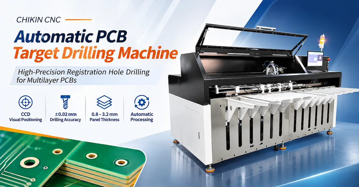
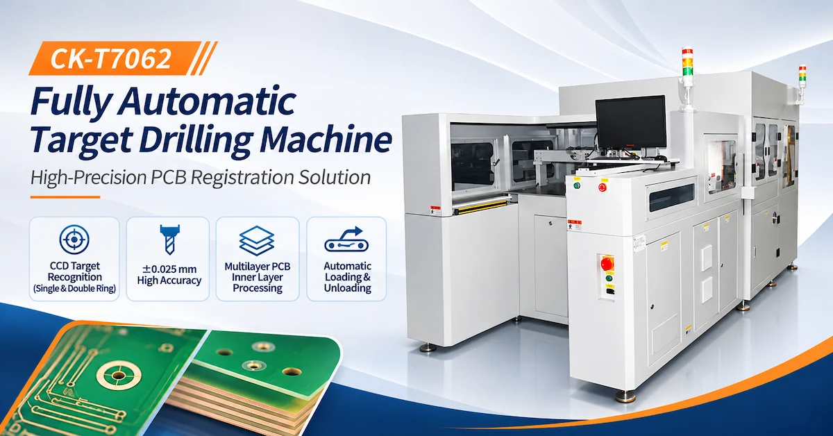
The CHIKIN CNC CK-T7062 features CCD single- and double-ring target recognition, a 60,000 RPM spindle, Excellon drill-data support, automatic loading and unloading, and published drilling offset, hole-size, and repeatability specifications of ±0.025 mm.
For industrial buyers, the main purchasing priorities are target recognition reliability, actual drilled-hole accuracy, panel compatibility, complete production cycle time, and integration with existing manufacturing equipment.
This guide explains how to evaluate the CK-T7062 and establish measurable factory acceptance requirements before purchasing.
Key Takeaways
-
CCD target recognition: Supports identification of single- and double-ring target patterns, including specified circular or hole-type references.
-
Precision drilling: The published drilling offset accuracy, hole-size tolerance, and repeat drilling accuracy are each ±0.025 mm.
-
Automated handling: The machine lists automatic loading and unloading with an independent panel-handling mechanism.
-
Production compatibility: Published plate dimensions range from 300 × 300 mm to 700 × 620 mm.
-
Tool management: A 60,000 RPM spindle, pneumatic tool changing, and tool-life reminders support the described drilling workflow.
-
Procurement priority: Actual recognition accuracy, drilled-hole quality, automation performance, and accepted production output must be verified through representative sample testing.
1. What Is a Fully Automatic Target Drilling Machine?
A fully automatic target drilling machine is specialized PCB manufacturing equipment designed to identify designated reference features and drill holes at calculated positions.
These holes may serve as registration or tooling references during subsequent manufacturing operations.
Unlike a conventional drilling machine that mainly follows programmed hole coordinates, a CCD-assisted target drilling system can locate specific visual references before processing.
Why Is Target Drilling Important in Multilayer PCB Manufacturing?
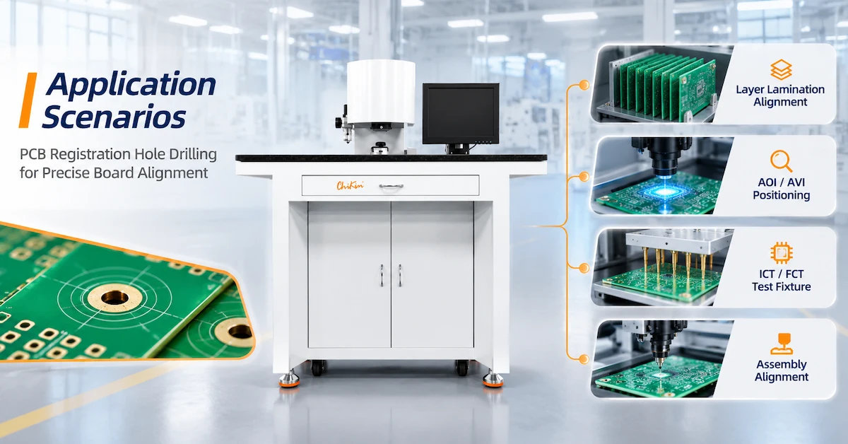
Multilayer PCB manufacturing involves several operations where positional consistency between panels or layers is important.
Differences in material movement, registration, or handling may affect subsequent alignment.
Accurately positioned registration holes can provide mechanical references for compatible fixtures and manufacturing processes.
Potential applications include:
-
Multilayer PCB registration-hole preparation.
-
Inner-layer target identification.
-
Panel positioning before selected downstream operations.
-
Tooling-hole processing.
-
Automated panel alignment workflows.
-
Manufacturing stages requiring repeatable reference positions.
The CK-T7062 is positioned for these types of applications, but its exact compatibility with a customer's material stack and manufacturing sequence must be confirmed.
Target Drilling vs Conventional PCB Drilling
| Comparison | Target Drilling Machine | Conventional PCB Drilling Machine |
|---|---|---|
| Main purpose | Reference and registration-hole processing | Vias, component holes, and tooling holes |
| Positioning reference | Visual targets and engineering data | Programmed hole coordinates |
| Vision identification | Central to the described target process | Depends on configuration |
| Production focus | Registration and alignment | General PCB hole production |
| Typical purchasing concern | Target recognition and hole placement | Hole quality and drilling capacity |
| Best application | Qualified registration workflows | General PCB drilling operations |
The two processes can complement one another, but they are not identical.
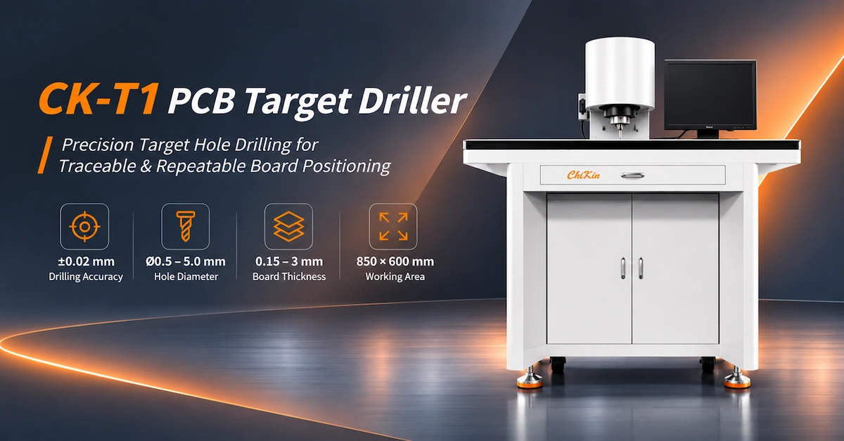
For broader drilling applications, manufacturers can also review the CHIKIN CNC PCB Target Drilling Machine.
2. CHIKIN CNC CK-T7062 Technical Specifications
CHIKIN CNC, operated by Shenzhen ChiKin Automation Equipment Co., Ltd., supplies PCB manufacturing and related industrial automation equipment.
The CK-T7062 is listed as a fully automatic target drilling machine featuring CCD recognition, controlled drilling, and automated panel handling.
CK-T7062 Machine Specification Table
| Technical Parameter | Published Specification |
|---|---|
| Model | CK-T7062 |
| Equipment type | Fully automatic target drilling machine |
| Machine dimensions | 3400 × 1850 × 1920 mm, solution-design dimensions |
| Working direction | Left in, right out |
| Operating interface | Chinese / English |
| Working height | 1000 mm |
| Maximum production plate | 700 × 620 mm |
| Minimum production plate | 300 × 300 mm |
| Production plate weight | ≤3 kg/panel |
| Production plate thickness | 0.1–3.2 mm |
| Published drilling efficiency | ≤1 hole/s, excluding loading and unloading |
| Drilling offset accuracy | ±0.025 mm |
| Drill-hole size tolerance | ±0.025 mm |
| Repeat drilling accuracy | ±0.025 mm |
| Recognition target diameter | 1.0–5.0 mm |
| Identification method | CCD single- and double-ring recognition |
| Engineering data | Excellon format |
| Spindle power | 1.8 kW |
| Spindle speed | 60,000 RPM |
| Number of drilling spindles | 1 |
| Tool change | Pneumatic |
| CCD acquisition range | 15 × 15 mm or greater |
| Electrical requirement | 220V, 50/60Hz, 3kVA |
| Air pressure requirement | 0.8 MPa |
| Listed air consumption | 1000 L/min |
| Machine weight | Approximately 2 tonnes |
Specifications are based on the supplied CK-T7062 datasheet. The exact operating configuration, testing conditions, material compatibility, and final machine dimensions should be confirmed before purchase.
Which Specifications Require Additional Verification?
The published production-plate dimensions are identified in the source table as applying to an aluminum base plate.
These values should not automatically be treated as verified performance limits for every FR4, copper-clad, or multilayer PCB construction.
Similarly, the 1.0–5.0 mm target diameter describes the recognition target specification. It should not be interpreted as the complete supported drilled-hole diameter range.
The datasheet also lists a spindle-collet torque value without a clear unit. Buyers should request a corrected technical specification before using that value in procurement.
3. How Does CCD Single- and Double-Ring Recognition Work?
CCD target recognition is one of the defining technical features of the CK-T7062.
The published machine specification identifies recognition of single- and double-ring patterns, including circular or hole-type targets.
A CCD system captures images of specified reference features and provides information used by the control system to determine the required drilling position.
Single-Ring vs Double-Ring Recognition
| Evaluation Factor | Single-Ring Target | Double-Ring Target |
|---|---|---|
| Visual structure | One defined ring feature | Two concentric or associated ring features |
| Recognition requirement | Identify the relevant reference center | Identify the required center from the specified pattern |
| Main consideration | Contrast and edge definition | Ring geometry and recognition rules |
| Processing risk | Poor visibility or damaged features | Incomplete or distorted ring patterns |
| Qualification method | Test actual production samples | Test actual production samples |
A double-ring target is not automatically more accurate than a single-ring target.
Recognition performance depends on camera resolution, lighting, software algorithms, target condition, and the specified measurement method.
Why Is CCD Recognition Important?
In manufacturing, the actual target position may differ slightly from its nominal program location.
A properly configured vision system can identify the reference feature and support the applicable position correction.
This can reduce reliance on manual visual alignment.
However, CCD recognition does not eliminate every source of positioning error.
Workpiece movement, mechanical calibration, drill runout, and tool condition can still influence the final hole.
4. How Does Excellon Drill-Data Support Improve Processing?
The CK-T7062 specification identifies support for reading engineering data in Excellon format.
Excellon data is commonly associated with PCB drilling information, including hole coordinates and tool-related instructions.
For manufacturing engineers, compatibility with approved drilling files can help connect engineering information with machine processing.
Typical Engineering Data Workflow
-
Prepare the approved drilling and registration requirements.
-
Export the supported engineering data.
-
Load the required file into the machine control system.
-
Verify dimensions, units, coordinates, and tool assignments.
-
Identify the actual target features through the CCD system.
-
Apply the supported alignment procedure.
-
Perform the programmed drilling operation.
-
Inspect the resulting holes.
What Should Buyers Verify?
Excellon support does not automatically guarantee compatibility with every CAM export or extended file variation.
Before purchasing, manufacturers should test actual production files.
The evaluation should cover coordinate interpretation, units, tooling data, alignment references, and error handling.
A complete engineering-file trial is more useful than a demonstration using only a simple test pattern.
5. How Does the CK-T7062 Automatic Processing Workflow Operate?
The CK-T7062 is positioned as an automated workstation with panel loading, CCD recognition, drilling, and unloading capabilities.
The supplied specifications identify a left-in, right-out working direction and an independent loading/unloading mechanism.
Recommended Process Evaluation
Step 1 — Automatic Panel Loading
A compatible panel is introduced into the working station.
The loading mechanism must support the specified dimensions, weight, and material conditions.
Step 2 — Workpiece Positioning
The board is positioned using the machine's approved locating and holding arrangement.
Panel stability is important before vision measurement.
Step 3 — CCD Target Recognition
The vision system identifies the required target pattern and establishes the applicable reference position.
Step 4 — Engineering Data Processing
The control system uses the approved drilling information to determine the required processing coordinates.
Step 5 — Target-Hole Drilling
The spindle performs the specified drilling operation using the qualified tool and cutting parameters.
Step 6 — Process Monitoring
The listed system supports real-time deviation monitoring and tool-change reminders.
The exact alarm logic should be confirmed during testing.
Step 7 — Automatic Panel Unloading
The processed panel is transferred from the machine according to the configured unloading sequence.
Step 8 — Quality Inspection
The drilled holes are evaluated against the required dimensions, positions, and material-quality criteria.
The exact automation and inspection sequence should be verified for the ordered machine.
6. What Does ±0.025 mm Drilling Accuracy Actually Mean?
The CK-T7062 datasheet publishes three separate accuracy-related values:
-
Drilling offset accuracy: ±0.025 mm.
-
Drill-hole size tolerance: ±0.025 mm.
-
Repeat drilling accuracy: ±0.025 mm.
Although the numerical values are identical, they describe different characteristics.
Accuracy and Quality Comparison
| Specification | Engineering Interpretation | Required Verification |
|---|---|---|
| Drilling offset accuracy | Positional deviation from the intended reference | Hole-center measurement |
| Drill-hole size tolerance | Variation in finished-hole dimension | Diameter measurement |
| Repeat drilling accuracy | Consistency across repeated drilling operations | Repeated sample testing |
| CCD recognition range | Area available for image acquisition | Vision-target demonstration |
| Target diameter | Supported recognition-feature size | Target compatibility testing |
Is ±0.025 mm a Guaranteed Finished-PCB Tolerance?
Not automatically.
The published values require defined test conditions.
Actual results may depend on material thickness, target quality, workpiece positioning, tool condition, spindle performance, and measurement method.
For multilayer PCB production, final layer-to-layer registration also depends on additional manufacturing operations.
Therefore, buyers should verify the CK-T7062's drilling performance separately from the finished board's overall registration results.
How Should Accuracy Be Tested?
Prepare representative panels containing the required target patterns.
Process multiple panels using a controlled machine configuration.
Measure the finished hole centers, diameters, and positional variation with appropriate calibrated equipment.
The test should cover the relevant production area rather than a single convenient location.
7. How Do Spindle Speed and Tool Management Affect Production?
The CK-T7062 lists one drilling spindle with a rated speed of 60,000 RPM and power of 1.8 kW.
It also lists pneumatic tool changing and a tool-life reminder function.
Why Does Spindle Speed Matter?
Spindle speed influences the cutting process, but higher RPM alone does not guarantee better drilling quality.
Appropriate settings depend on drill diameter, material construction, cutting depth, feed rate, and tool design.
The selected tool must be compatible with the spindle and holding system.
What Is the Difference Between Tool Changing and Tool-Life Monitoring?
Pneumatic tool changing describes a mechanism used to change or release compatible tools.
Tool-life monitoring tracks the defined service interval or usage condition.
The CK-T7062 datasheet identifies an early reminder before the established tool-life limit.
This does not establish that the system directly measures cutting-edge wear or detects every possible drill failure.
Tool Management Evaluation
| Feature | Published Information | Buyer Check |
|---|---|---|
| Spindle speed | 60,000 RPM | Suitable operating conditions |
| Spindle power | 1.8 kW | Compatibility with material and tool |
| Tool change | Pneumatic | Actual change sequence |
| Tool-life reminder | Early alarm before replacement limit | Reminder logic and operator response |
| Tool holder | 3.175 mm referenced in the collet specification | Complete interface and approved tools |
| Number of spindles | 1 | Actual processing capacity |
For factories processing different target-hole patterns, tool handling and maintenance requirements should be included in the equipment evaluation.
8. Is One Hole per Second the Actual Machine Throughput?
The CK-T7062 specification lists ≤1 hole/s as a drilling-efficiency figure and explicitly excludes loading and unloading time.
This should not be interpreted as one completed PCB panel per second.
Actual production output also depends on target recognition, positioning movements, hole count, panel transfer, and inspection.
Complete Production Cycle
Total Cycle Time = Loading + Positioning + CCD Recognition + Drilling + Unloading + Required Inspection
Additional time may be required for tool replacement, changeovers, or alarms.
Production Capacity Factors
| Factor | Influence on Output |
|---|---|
| Holes per panel | Determines drilling operations |
| CCD recognition time | Adds alignment time |
| Panel dimensions | Affects handling and movement |
| Automatic loading | Influences transfer efficiency |
| Tool changes | May interrupt production |
| Material characteristics | Influence drilling conditions |
| Inspection requirements | Add verification time |
| Production interruptions | Reduce available machine time |
What Should Purchasing Managers Measure?
Use actual panels containing representative target patterns.
Record the complete production cycle and inspect the resulting holes.
For production planning:
Accepted Panels per Hour = Completed Panels per Hour × Acceptance Rate
This metric provides a more realistic basis for comparing equipment than nominal drilling efficiency.
9. What Quality Problems Can Occur During Automatic Target Drilling?
Target drilling involves both optical recognition and mechanical processing.
Defects can arise from either part of the system.
Troubleshooting Matrix
| Problem | Possible Cause | Recommended Verification |
|---|---|---|
| Target not recognized | Poor contrast, contamination, damaged pattern | Inspect CCD images and target condition |
| Incorrect hole position | Alignment, calibration, panel movement | Verify reference coordinates |
| Oversized hole | Tool runout or tool diameter | Inspect tool and finished hole |
| Rough hole edges | Unsuitable drilling conditions | Check material and cutting parameters |
| Incomplete drilling | Incorrect depth or setup | Review tool length and process settings |
| Panel damage | Inadequate support or excessive loading | Inspect holding and contact areas |
| Inconsistent results | Fixture or calibration variation | Repeat production testing |
| Handling interruption | Loading or unloading problem | Review sensors and transfer mechanism |
Why Is Panel Support Important?
Even if the CCD system identifies a target accurately, the workpiece can move before or during drilling if it is not properly supported.
This can affect the position of the finished hole.
A qualified process should therefore evaluate target recognition and mechanical workholding together.
10. CK-T7062 Factory Acceptance Test: What Should Buyers Verify?
A Factory Acceptance Test (FAT) should establish whether the actual machine configuration meets the buyer's production requirements.
The test should use representative panels, target patterns, and drilling files.
CK-T7062 FAT Checklist
| Test Item | Recommended Acceptance Method |
|---|---|
| Model verification | Confirm CK-T7062 configuration |
| Panel dimensions | Test required sizes within the published range |
| Panel weight | Verify intended handling loads |
| Material compatibility | Process actual production material |
| CCD recognition | Test single- and double-ring targets |
| Target size | Verify applicable 1.0–5.0 mm recognition features |
| Drilling offset | Measure finished-hole positions |
| Hole diameter | Compare with specified tolerances |
| Repeatability | Test multiple panels and positions |
| Excellon files | Import and process actual production data |
| Automatic loading | Demonstrate reliable panel transfer |
| Automatic unloading | Verify completed-panel handling |
| Tool changing | Demonstrate pneumatic operation |
| Deviation monitoring | Verify the relevant alarm behavior |
| Cycle time | Record full operating cycle |
| Safety | Check guarding, interlocks, and emergency controls |
| Documentation | Review machine manuals and test records |
Recommended Sample Validation Procedure
1. Prepare production samples. Provide actual panel materials and reference patterns.
2. Define acceptance criteria. Specify hole-center accuracy, diameter tolerance, recognition requirements, and material condition.
3. Import engineering data. Verify the production Excellon files.
4. Perform repeated trials. Test representative panel sizes and target locations.
5. Inspect finished holes. Measure positional and dimensional results.
6. Validate automation. Record loading, drilling, unloading, and interruption behavior.
7. Document results. Retain the approved machine configuration, operating parameters, and inspection records.
Applicable editions of IPC-A-600 and IPC-6012 may provide relevant finished rigid-board quality references where required by the customer.
However, these standards do not independently certify the drilling machine or establish universal target-hole tolerances.
11. What Should Buyers Check Before Installing the CK-T7062?
Automatic production equipment requires more installation planning than a standalone bench-top machine.
The CK-T7062 is designed around a left-in, right-out material flow.
Factory Installation Requirements
| Requirement | Published Specification |
|---|---|
| Machine dimensions | 3400 × 1850 × 1920 mm, solution design |
| Working height | 1000 mm |
| Material flow | Left in, right out |
| Electrical supply | 220V, 50/60Hz, 3kVA |
| Air pressure | 0.8 MPa |
| Listed air consumption | 1000 L/min |
| Machine weight | Approximately 2 tonnes |
| Exhaust connection | Ø50 mm pipe listed |
| Dust collection | 10 m³/hour listed; verify final requirement |
| Operating environment | General workshop environment stated |
Why Does Line Integration Matter?
A fully automatic target drilling machine must fit the surrounding production process.
Important considerations include available floor space, upstream and downstream handling, transfer height, material orientation, and operator access.
The published dimensions are described as solution-design dimensions, so final installation drawings should be confirmed for the ordered configuration.
Safety and Environmental Considerations
The machine photographs show an enclosure, inspection windows, operator controls, and emergency-stop components.
These features should be reviewed as part of the complete safety assessment.
Relevant industrial machinery references include ISO 12100 for risk assessment and IEC 60204-1 for electrical equipment of machines, where applicable.
The final guarding, interlock, extraction, and electrical arrangements should be verified for the delivered system.
12. Fully Automatic vs Semi-Automatic Target Drilling: Which Is Better?
Automation is valuable when it addresses an actual production bottleneck.
However, more automation does not automatically produce better drilling accuracy.
| Evaluation | Manual / Semi-Automatic Process | Fully Automatic CK-T7062 |
|---|---|---|
| Loading | Greater operator involvement | Automatic loading listed |
| Target recognition | Depends on equipment | CCD recognition specified |
| Drilling | Depends on machine | 60,000 RPM spindle specified |
| Unloading | May require manual handling | Automatic unloading listed |
| Process monitoring | Depends on control system | Real-time deviation monitoring listed |
| Investment | Often lower complexity | Greater integration requirements |
| Best fit | Lower-volume or flexible workflows | Repeated production with suitable panel formats |
When Is Full Automation Worth Considering?
The CK-T7062 is particularly relevant where factories experience repeated manual alignment, inconsistent handling, or difficulty maintaining continuous production.
However, the financial benefit should be calculated from actual accepted output, labor requirements, downtime, and equipment costs.
A useful metric is:
Drilling Cost per Accepted Panel = Total Allocated Processing Cost ÷ Accepted Panels
The calculation should use qualification data rather than estimated productivity improvements.
13. CK-T7062 RFQ Checklist for Overseas PCB Manufacturers
A complete request for quotation helps the supplier evaluate the actual manufacturing application.
Technical RFQ Checklist
| Required Information | Buyer Should Provide |
|---|---|
| PCB material | Actual production substrate and layer construction |
| Panel dimensions | Minimum and maximum sizes |
| Panel thickness | Required material range |
| Panel weight | Maximum expected weight |
| Target type | Single ring, double ring, or other |
| Target dimensions | Diameter and feature drawing |
| Hole requirements | Drill diameter, position, and tolerance |
| Engineering files | Representative Excellon data |
| Production target | Accepted panels per hour |
| Material handling | Required loading and unloading interface |
| Tooling | Drill and collet requirements |
| Quality inspection | Measurement and acceptance method |
| Factory utilities | Electricity, air, and extraction |
| Installation layout | Available space and transfer direction |
| Commercial information | Quantity, destination, and service requirements |
Why Consider CHIKIN CNC?
CHIKIN CNC supplies PCB manufacturing and industrial automation equipment, including drilling, routing, and target registration solutions.
The CK-T7062 provides a specific configuration for manufacturers evaluating vision-guided target drilling and automated handling.
Buyers can also review the company's manufacturing and service capabilities.
For the most accurate recommendation, technical evaluation should begin with actual panels and drilling files rather than a generic equipment request.
Request a CK-T7062 Technical Evaluation and Quotation
If your factory needs automated registration-hole drilling, prepare your panel specifications, target patterns, engineering files, and required production output.
Review the CHIKIN CNC Fully Automatic Target Drilling Machine.
Contact CHIKIN CNC for a CK-T7062 Configuration Review and Quotation.
A complete technical brief will help clarify equipment compatibility, automation requirements, and factory acceptance testing.
14. Frequently Asked Questions About Fully Automatic Target Drilling Machines
1. What is a fully automatic target drilling machine used for?
It is used to identify designated reference features and drill compatible registration or tooling holes. Automated configurations can also handle panel loading and unloading within a defined manufacturing workflow.
2. What is the maximum panel size supported by the CK-T7062?
The published maximum is 700 × 620 mm, and the minimum is 300 × 300 mm. These dimensions are listed for an aluminum base plate, so compatibility with other PCB materials should be confirmed.
3. What drilling accuracy does the CK-T7062 offer?
The datasheet lists ±0.025 mm drilling offset accuracy, drill-hole size tolerance, and repeat drilling accuracy. Actual performance must be tested under agreed material and measurement conditions.
4. Does the CK-T7062 support CCD target recognition?
Yes. The specification identifies CCD recognition of single- and double-ring targets, including circular or hole-type features.
5. What target diameter can the machine identify?
The published target diameter range is 1.0–5.0 mm. This refers to the recognition target and should not automatically be interpreted as the supported drill-hole diameter range.
6. Can the CK-T7062 read Excellon drilling files?
The specification lists Excellon engineering-data support. Buyers should test their actual file format, coordinate interpretation, tooling information, and required processing functions.
7. What is the spindle speed of the CK-T7062?
The machine lists one drilling spindle operating at 60,000 RPM with a published power rating of 1.8 kW. Actual cutting parameters depend on the selected material and drilling tool.
8. Does the machine support automatic loading and unloading?
Yes. Automatic loading and unloading are included in the published configuration. The actual handling sequence, compatible panel conditions, and integration interfaces should be verified.
9. Is the published drilling efficiency equal to actual production throughput?
No. The listed ≤1 hole/s efficiency excludes loading and unloading. Complete production throughput must also account for recognition, positioning, inspection, tool changes, and interruptions.
10. What should I provide when requesting a CK-T7062 quotation?
Provide the panel material, dimensions, thickness, target geometry, Excellon files, required hole accuracy, production volume, utility conditions, and factory layout. Sample processing and an agreed FAT procedure are recommended before purchase.
Conclusion
Selecting the right fully automatic target drilling machine requires a complete understanding of CCD target recognition, registration-hole accuracy, spindle capability, automated handling, and factory integration.
The CHIKIN CNC CK-T7062 offers a published configuration featuring CCD single- and double-ring recognition, a 60,000 RPM spindle, Excellon data support, automatic loading and unloading, and ±0.025 mm specifications for drilling offset, hole size, and repeatability.
These characteristics make it a candidate for PCB manufacturers seeking more standardized registration-hole processing and reduced reliance on manual panel handling.
However, a successful equipment investment depends on more than published technical values.
Buyers should confirm the actual material compatibility, recognize the distinction between target size and drilled-hole size, evaluate finished-hole quality, and measure complete accepted production output.
A documented Factory Acceptance Test using representative panels is essential for establishing the machine's practical suitability.
For overseas B2B manufacturers evaluating automated PCB registration equipment, CHIKIN CNC provides the CK-T7062 within its wider PCB manufacturing equipment portfolio.
Explore the CK-T7062 Fully Automatic Target Drilling Machine or contact CHIKIN CNC for an application-specific technical evaluation and quotation.
Share your PCB registration drawings, target specifications, panel dimensions, Excellon files, and production requirements to evaluate a machine configuration suited to your manufacturing workflow.