



Quick Answer: Which PCB Target Drilling Machine Should You Choose?
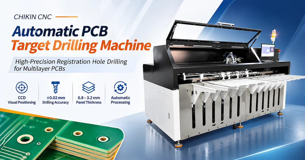
A PCB target drilling machine uses controlled positioning and drilling to create reference holes for PCB registration, tooling, and subsequent manufacturing operations. CCD-equipped configurations can identify actual target positions before drilling, helping reduce dependence on manual alignment.
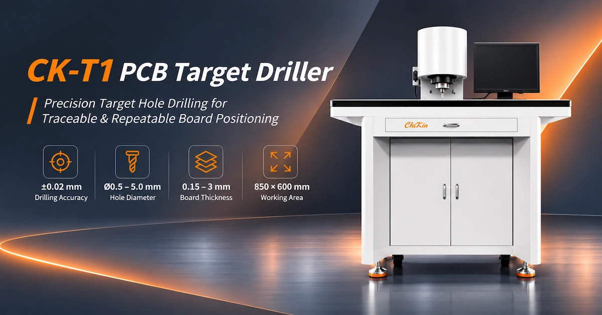
The CHIKIN CNC CK-T1300, CK-T900, and CK-T700 provide different processing areas and machine configurations. Their published maximum processing areas are 1300 × 650 mm, 900 × 650 mm, and 700 × 550 mm, respectively.
Choose according to your largest panel size, required hole tolerance, material thickness, tooling configuration, and production demand—not machine dimensions or spindle speed alone.
For multilayer PCB factories, the most reliable purchasing process combines machine specification review, real-panel sample drilling, dimensional inspection, and documented factory acceptance testing.
Key Engineering Takeaways
-
Three processing formats: CK-T1300 supports the largest published working area, followed by CK-T900 and CK-T700.
-
Published drilling capability: The comparative datasheet lists Ø0.5–5.0 mm drilling holes and ±0.02 mm drilling accuracy.
-
Spindle configuration: The CK-T1300 and CK-T900 columns list 40,000 RPM and 750W; the CK-T700 column identifies a 60,000 RPM, 1200W Plus configuration.
-
CCD positioning: The product family is promoted for vision-assisted target and fiducial recognition, but target recognition should be validated using actual production artwork.
-
Quality requirements: Positioning accuracy, drilling accuracy, hole-diameter deviation, and repeatability are different performance measurements.
-
Procurement priority: Obtain machine-specific configuration details, real drilling results, and approved acceptance criteria before purchase.
1. What Is a PCB Target Drilling Machine Used For?
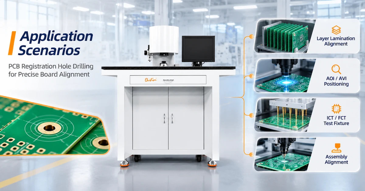
A PCB target drilling machine produces accurately located reference holes in suitable printed circuit board panels.
These holes may provide positioning references for manufacturing fixtures, alignment systems, and selected downstream processes.
In multilayer PCB manufacturing, accurate registration helps control the relationship between a panel and the intended tooling coordinates.
A vision-guided machine may identify designated target marks and calculate the required drilling position before processing.
Typical Applications
-
Multilayer PCB registration-hole drilling.
-
Inner-layer panel positioning.
-
Target and fiducial reference processing.
-
Tooling-hole preparation.
-
Suitable copper-clad laminate processing.
-
Rigid PCB production requiring consistent locating features.
-
Registration-related operations before qualified downstream manufacturing stages.
Why Is Target Drilling Different from General PCB Drilling?
A conventional PCB drilling machine primarily produces vias, component holes, and other programmed holes.
A dedicated target drilling machine focuses on locating and processing reference features that support alignment.
| Comparison | PCB Target Drilling | Conventional PCB Drilling |
|---|---|---|
| Main objective | Registration and reference holes | Functional and mechanical holes |
| Position reference | Target or fiducial alignment where supported | Programmed coordinates |
| Typical buyer | Multilayer PCB process engineer | PCB drilling production manager |
| Main concern | Registration-hole placement | Hole quality and drilling productivity |
| CCD relevance | Important in vision-guided configurations | Configuration-dependent |
These systems are complementary rather than interchangeable.
2. CK-T1300 vs CK-T900 vs CK-T700: Complete Model Comparison
CHIKIN CNC lists three models within its automatic target drilling machine specification.
The main difference is the published processing envelope and associated machine configuration.
PCB Target Drilling Machine Specification Comparison
| Specification | CK-T1300 | CK-T900 | CK-T700 |
|---|---|---|---|
| CNC system | CHIKIN CNC | CHIKIN CNC | CHIKIN CNC |
| Maximum processing area | 1300 × 650 mm | 900 × 650 mm | 700 × 550 mm |
| Machine dimensions (L × W × H) | 2800 × 1940 × 1650 mm | 2050 × 1940 × 1650 mm | 1600 × 1800 × 1650 mm |
| Machine weight | 1350 kg | 950 kg | 850 kg |
| Processing thickness | 0.8–3.2 mm | 0.8–3.2 mm | 0.8–3.2 mm |
| Drilling-hole diameter | Ø0.5–5.0 mm | Ø0.5–5.0 mm | Ø0.5–5.0 mm |
| Published drilling accuracy | ±0.02 mm | ±0.02 mm | ±0.02 mm |
| Published drilling time | 0.5 s/hole | 0.5 s/hole | 0.5 s/hole |
| Hole-diameter deviation | ≤0.025 mm | ≤0.025 mm | ≤0.025 mm |
| Spindle speed shown | 40,000 RPM | 40,000 RPM | Plus: 60,000 RPM |
| Spindle power shown | 750W | 750W | Plus: 1200W |
| Z-axis arrangement shown | Cylinder | Cylinder | Plus: ballscrew transmission |
| Maximum power demand shown | 3kVA | 3kVA | Plus: 5kVA |
The model comparison is based on the supplied CHIKIN specification table. Plus specifications shown in the CK-T700 column require confirmation of the exact quoted configuration.
The datasheet additionally lists single-phase AC220V ±10%, dry compressed air of at least 0.5MPa, and an optional auxiliary unloading device.
Which Model Is Best for Your Factory?
CK-T1300 — Larger panels
Evaluate this model when the required processing envelope exceeds the capacities of the smaller machines.
CK-T900 — Medium-width panels
Consider it when the board mix fits within 900 × 650 mm and the factory does not require the larger CK-T1300 processing area.
CK-T700 — Smaller panels
Evaluate the 700 × 550 mm format when it accommodates the complete production range. Confirm whether the Plus spindle and Z-axis configuration is required and included.
A larger machine is not automatically more accurate or more productive. The appropriate model is the smallest suitable configuration that satisfies the full manufacturing requirement.
3. How Does CCD Target Recognition Improve PCB Registration?
CCD-based target recognition allows a machine to locate designated visual features on a workpiece.
Rather than relying exclusively on nominal drawing coordinates, a qualified vision system can identify actual reference positions and support the machine's alignment process.
Typical Vision-Guided Workflow
-
Position the PCB panel on the approved fixture.
-
Capture images of designated target features.
-
Identify the applicable target centers.
-
Calculate the required coordinate adjustment.
-
Move the spindle to the drilling position.
-
Drill the specified registration holes.
-
Inspect the finished results.
What Determines CCD Recognition Reliability?
| Factor | Why It Matters |
|---|---|
| Target geometry | Determines the feature to be recognized |
| Target contrast | Influences image interpretation |
| Surface finish | Can affect reflected light |
| Target contamination | May interfere with recognition |
| Camera resolution | Influences measurable image detail |
| Lighting | Affects edge and feature visibility |
| Calibration | Connects visual coordinates to machine motion |
| Workpiece stability | Prevents movement after recognition |
The product description highlights CCD vision, but the comparative model table does not identify the exact camera model, resolution, or recognition algorithm for each configuration.
These details should be confirmed during technical evaluation.
Can CCD Cameras Detect Buried Internal Targets?
Not through opaque laminate material using ordinary visible-light imaging.
If a manufacturing application requires detecting copper targets hidden inside an opaque multilayer construction, buyers should clarify whether an appropriate X-ray or other subsurface recognition method is needed.
Do not assume that a CCD target drilling machine includes X-ray imaging.
4. How Should Buyers Interpret the Drilling Accuracy Specifications?
Accuracy is among the most important purchasing criteria for a PCB target drilling machine.
However, different measurements describe different performance characteristics.
Drilling Accuracy vs Positioning Accuracy
| Measurement | Description |
|---|---|
| Positioning accuracy | Difference between commanded and achieved machine position |
| Repeatability | Consistency of repeated machine movement or processing |
| Drilling accuracy | Actual drilled-hole location relative to the specified reference |
| Hole-diameter deviation | Variation in the finished hole diameter |
| CCD recognition accuracy | Accuracy of target detection under defined conditions |
The CK-T model datasheet lists ±0.02 mm drilling accuracy and ≤0.025 mm hole-diameter deviation.
Separately, CHIKIN's general product description references ±0.005 mm positioning/repeatability.
These figures must not be treated as interchangeable.
What Should Be Included in an Accuracy Test?
The buyer should define:
-
Actual PCB material and thickness.
-
Panel dimensions.
-
Target diameter and geometry.
-
Required drilling-hole diameter.
-
Hole-position tolerance.
-
Measurement datum.
-
Inspection equipment.
-
Number of test panels.
-
Required acceptance rate.
The supplier should demonstrate performance against these agreed conditions.
A machine's positioning specification does not automatically guarantee the same tolerance in a completed PCB panel.
5. What Hole Sizes and PCB Materials Can These Machines Process?
The comparative specification lists a drilling-hole diameter range of Ø0.5–5.0 mm and processing thickness of 0.8–3.2 mm.
The material field includes single- and double-sided substrates, copper and aluminum substrates, and other metal-based materials.
Material Evaluation Matrix
| Material | Relevant Application | Main Verification |
|---|---|---|
| Single-sided PCB | Tooling and registration holes | Hole position and edge condition |
| Double-sided PCB | Reference-hole preparation | Copper and laminate integrity |
| FR4 rigid PCB | Qualified registration drilling | Drill wear and fiber breakout |
| Copper-based substrate | Application-specific drilling | Cutting load and hole quality |
| Aluminum-based substrate | Tooling-hole processing | Burrs and tool compatibility |
| Multilayer PCB | Registration-related drilling | Layer construction and alignment |
Material suitability must be verified using actual production samples.
A machine capable of drilling standard FR4 is not automatically qualified for aluminum or copper substrates using the same tool and cutting parameters.
Why Does Material Thickness Matter?
Greater thickness changes the cutting engagement and chip evacuation requirements.
Thinner panels may present different handling and clamping challenges.
For both conditions, correct tooling and workpiece support are essential.
Buyers should test representative material thicknesses within their intended production range.
6. How Do Spindle Speed and Z-Axis Control Affect Drilling?
The published CK-T series includes different spindle and Z-axis configurations.
40,000 RPM vs 60,000 RPM
Higher spindle speed does not automatically mean higher finished-hole accuracy.
The result depends on tool diameter, material, feed rate, spindle runout, and the full cutting setup.
For the CK-T700, the datasheet identifies a 60,000 RPM Plus configuration. Buyers should confirm whether that is an upgraded version and what additional equipment it includes.
Cylinder vs Ballscrew Z-Axis
A cylinder-based Z-axis and a ballscrew-driven Z-axis use different motion-control arrangements.
Their suitability depends on the required movement profile, drilling depth, material, and process design.
Neither system should be declared universally superior without comparable testing.
What Should Buyers Check?
-
Spindle model and rated speed.
-
Spindle power.
-
Supported drill-bit sizes.
-
Tool-holder dimensions.
-
Available Z-axis travel.
-
Depth-setting method.
-
Tool-change procedure.
-
Spindle runout.
-
Tool maintenance and replacement requirements.
The general CHIKIN target-drilling product description mentions automatic tool changing, tool-length detection, diameter detection, and broken-tool detection.
However, these functions are not individually itemized in the three-model comparison table. Confirm which are standard, optional, or applicable to each model before ordering.
7. Can the Machine Really Drill One Hole Every 0.5 Seconds?
The comparative specification states 0.5 s/hole.
This is a published drilling-time reference, not a guaranteed complete production cycle.
Actual PCB throughput depends on recognition, positioning, material handling, drilling, and inspection.
Production Cycle Calculation
Total Panel Cycle Time = Loading + Alignment + Positioning + Drilling + Inspection + Unloading
For example, a panel requiring several registration holes will also need the relevant positioning movements.
The completed production rate must therefore be measured using the real hole pattern.
What Affects Accepted Output?
| Factor | Effect |
|---|---|
| Number of holes | More drilling operations |
| Hole positions | Different positioning distances |
| CCD recognition | Additional alignment time |
| Tool changes | Possible interruptions |
| Loading method | Operator or automation time |
| Material | Different qualified cutting parameters |
| Inspection | Required quality-control time |
For production planning:
Accepted Panels per Hour = Completed Panels per Hour × Acceptance Rate
A machine should be evaluated by accepted production output rather than nominal single-hole drilling time.
8. CK-T Series vs CK-T7062: Which Target Drilling Platform Fits?
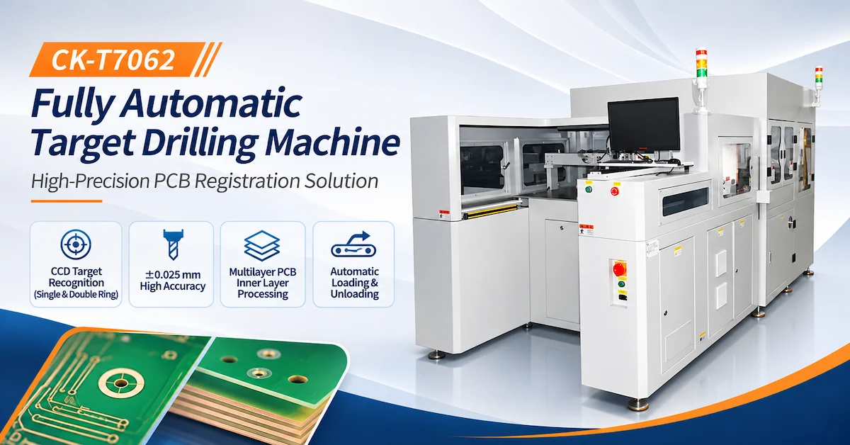
CHIKIN CNC also lists the CK-T7062 Fully Automatic Target Drilling Machine.
Although both equipment families address PCB registration, their published configurations differ.
| Evaluation | CK-T1300 / CK-T900 / CK-T700 | CK-T7062 |
|---|---|---|
| Core function | Target and registration drilling | Automated target and registration drilling |
| Main selection factor | Processing area and model configuration | Vision-guided processing and inline handling |
| Published drilling accuracy | ±0.02 mm | ±0.025 mm drilling offset |
| Target recognition | CCD described in product family | Single/double-ring CCD recognition specified |
| Handling | Auxiliary unloading listed as optional | Automatic loading and unloading listed |
| Engineering data | Confirm supported formats | Excellon support specified |
| Best purchasing approach | Match panel size and tooling | Validate full automation and integration |
The two models' accuracy figures use different specification descriptions and should not be treated as a direct performance ranking.
When Should You Consider the CK-T7062?
It may be a stronger candidate when automatic panel transfer, specified recognition patterns, and integration with surrounding equipment are central requirements.
When Should You Consider the CK-T Series?
These models are particularly worth evaluating when the required processing area and drilling configuration are the main selection criteria.
The CK-T1300 may be relevant when the production format exceeds the smaller alternatives.
The final choice should be established through representative samples and a complete equipment proposal.
9. Common PCB Target Drilling Problems and Quality Risks
Even with CCD recognition, target drilling quality depends on the complete mechanical and process setup.
| Problem | Possible Cause | Recommended Check |
|---|---|---|
| Target not recognized | Poor contrast or damaged target | Camera image and lighting |
| Hole offset | Alignment or calibration error | Datum and coordinate verification |
| Oversized holes | Tool runout or unsuitable cutter | Spindle and tool inspection |
| Rough hole edges | Material or cutting-condition mismatch | Drill geometry and feed |
| Inconsistent hole positions | Board movement or fixture variation | Clamping and calibration |
| Tool breakage | Excessive cutting load or runout | Tool condition and parameters |
| Incomplete drilling | Incorrect depth or tool setting | Z-axis and tool-length setup |
How Can Factories Reduce Rework?
Use representative sample boards during setup and qualification.
Maintain a documented inspection plan and record the approved cutting parameters.
When a defect appears, investigate target recognition, machine positioning, tooling, and workpiece support separately rather than changing several variables simultaneously.
For more background, CHIKIN's PCB Target Drilling Machine Manufacturer Guide discusses the importance of machine construction, CCD recognition, and supplier engineering capability.
10. Factory Acceptance Test: How to Validate the Selected Model
A Factory Acceptance Test (FAT) helps establish whether the machine satisfies the agreed manufacturing requirements before shipment.
Recommended FAT Checklist
| Test Item | Acceptance Requirement |
|---|---|
| Machine model | Verify CK-T1300, CK-T900, or CK-T700 |
| Processing area | Confirm the required panel dimensions |
| Material thickness | Test production material within the stated range |
| Drilling diameter | Test relevant Ø0.5–5.0 mm holes |
| Drilling accuracy | Measure hole-center deviation |
| Hole diameter | Measure finished-hole size |
| Repeatability | Compare repeated samples |
| CCD recognition | Test actual reference features |
| Spindle configuration | Verify rated speed and installed hardware |
| Z-axis control | Demonstrate the ordered arrangement |
| Tool management | Verify all contracted functions |
| Processing time | Record actual hole and panel cycle times |
| Electrical supply | Confirm the installed configuration |
| Safety | Verify guarding and emergency controls |
| Documentation | Review manuals and inspection records |
Sample Validation Procedure
Step 1: Select representative production panels and target geometries.
Step 2: Define hole positions, diameters, and acceptance limits.
Step 3: Verify the required machine and tool configuration.
Step 4: Process multiple test panels using controlled settings.
Step 5: Measure the finished holes with calibrated equipment.
Step 6: Evaluate recognition failures, tool issues, and actual cycle time.
Step 7: Record the final approved conditions.
For rigid printed boards, relevant editions of IPC-A-600 and IPC-6012 may support applicable finished-board inspection requirements when specified by the customer.
These standards do not independently certify the drilling equipment.
11. Installation Requirements and Total Equipment Cost
Before ordering, confirm that the machine fits the factory's available space, electrical supply, pneumatic system, and maintenance requirements.
The CK-T series specification lists single-phase AC220V ±10% and dry air pressure of at least 0.5MPa.
The exact power demand and auxiliary equipment depend on the quoted configuration.
Total Cost of Ownership Checklist
| Cost Factor | Buyer Consideration |
|---|---|
| Machine purchase price | Model and included functions |
| Processing area | Required production format |
| Spindle and Z-axis | Standard or upgraded configuration |
| Cutting tools | Consumption and replacement |
| Fixtures | Material and target compatibility |
| Extraction | Dust-control requirements |
| Electricity and air | Factory utility costs |
| Inspection | Quality measurement and testing |
| Maintenance | Spare parts and downtime |
| Installation | Commissioning and operator training |
A useful economic metric is:
Drilling Cost per Accepted Panel = Total Allocated Drilling Cost ÷ Accepted Panels
A higher-cost machine may be justified when it provides a necessary processing area or verified operational benefit.
However, the investment should be evaluated from actual production data rather than assumptions about spindle speed.
12. PCB Target Drilling Machine RFQ Checklist
A detailed request for quotation allows the manufacturer to evaluate the actual application.
| Information | What Buyers Should Provide |
|---|---|
| PCB material | FR4, copper-based, aluminum-based, or other |
| Panel dimensions | Minimum and maximum sizes |
| Material thickness | Actual production range |
| Target geometry | Shape, dimensions, and reference drawing |
| Required hole size | Diameter and tolerance |
| Positional accuracy | Required drilling-hole deviation |
| Production volume | Panels and holes per shift |
| Tool specifications | Diameter, shank, and preferred tooling |
| CCD requirements | Actual target appearance and recognition conditions |
| Handling | Manual or requested automated unloading |
| Utility requirements | Electrical and pneumatic supply |
| Inspection | Sample and FAT acceptance criteria |
| Commercial requirements | Delivery destination, warranty, and support scope |
Request a CHIKIN CNC Technical Review
CHIKIN CNC, operated by Shenzhen ChiKin Automation Equipment Co., Ltd., supplies PCB drilling and related manufacturing equipment.
The CK-T1300, CK-T900, and CK-T700 provide different processing-area and spindle-configuration options for suitable target drilling applications.
Explore the CHIKIN PCB Target Drilling Machine to review the available product family.
For a more accurate purchasing discussion, send your PCB drawings, panel dimensions, target features, required hole accuracy, and production output.
Contact CHIKIN CNC for Model Selection, Sample Drilling, and a Technical Quotation.
Before placing an order, confirm the final model specifications, optional features, factory acceptance conditions, warranty coverage, and delivery arrangements.
13. Frequently Asked Questions About PCB Target Drilling Machines
1. What is a PCB target drilling machine?
It is equipment used to drill reference or registration holes in suitable PCB materials. Vision-guided configurations may locate designated targets before drilling to support controlled hole placement.
2. What is the difference between CK-T1300 and CK-T900?
The primary published difference is processing area. The CK-T1300 lists 1300 × 650 mm, while the CK-T900 lists 900 × 650 mm. Machine dimensions and weight also differ.
3. What is the maximum processing area of the CK-T700?
The CK-T700 specification lists 700 × 550 mm. Its actual usable working area and fixture requirements should be verified for the ordered configuration.
4. What drilling accuracy does the CK-T series offer?
The comparative model datasheet lists ±0.02 mm drilling accuracy and hole-diameter deviation of no more than 0.025 mm. Actual results require testing under defined conditions.
5. Is ±0.005 mm positioning accuracy the same as ±0.02 mm drilling accuracy?
No. Positioning accuracy and finished drilling accuracy describe different characteristics. The supplier should specify the measurement method and applicable model for each value.
6. What hole diameters can these machines drill?
The comparative model table lists Ø0.5–5.0 mm. Smaller or larger drilling-tool capabilities mentioned in general product descriptions should not be assumed to apply to every CK-T configuration.
7. Does every CK-T model have a 60,000 RPM spindle?
No. The published comparison lists 40,000 RPM for the CK-T1300 and CK-T900, while a 60,000 RPM Plus specification appears in the CK-T700 column. Confirm the exact ordered version.
8. Can a PCB target drilling machine process aluminum substrates?
Aluminum and other metal-based substrates are included in the product's stated application materials. Actual suitability depends on material construction, tooling, and validated cutting parameters.
9. Is automatic unloading standard equipment?
The supplied comparative specification lists an auxiliary unloading device as optional. Buyers should confirm the loading and unloading scope of the selected configuration.
10. How should I choose between CK-T1300, CK-T900, and CK-T700?
Start with the largest required panel and supported material thickness. Then compare target recognition, drilling tolerances, spindle and Z-axis configuration, operating utilities, and actual sample results before requesting a final quotation.
Conclusion
Choosing the right PCB target drilling machine requires more than comparing processing area, spindle speed, or equipment price.
For multilayer PCB manufacturers, the key factors are target recognition reliability, finished-hole accuracy, material compatibility, workpiece positioning, and accepted production output.
The CHIKIN CNC CK-T1300, CK-T900, and CK-T700 provide three different processing formats, allowing buyers to evaluate the configuration that best matches their panel dimensions and manufacturing requirements.
The published specifications include Ø0.5–5.0 mm drilling holes, ±0.02 mm drilling accuracy, and different spindle and machine-size configurations.
However, final equipment selection should be based on actual production conditions and verified sample drilling rather than catalog claims alone.
A documented Factory Acceptance Test helps confirm whether the chosen machine meets the required quality and productivity criteria.
For overseas PCB factories evaluating registration-hole processing equipment, CHIKIN CNC provides target drilling solutions within its wider PCB manufacturing equipment portfolio.
Review the CHIKIN PCB Target Drilling Machine or contact CHIKIN CNC for an application-specific machine comparison and quotation.
Share your panel drawings, target patterns, material specifications, required tolerances, and production volume to identify the most suitable configuration for your manufacturing workflow.