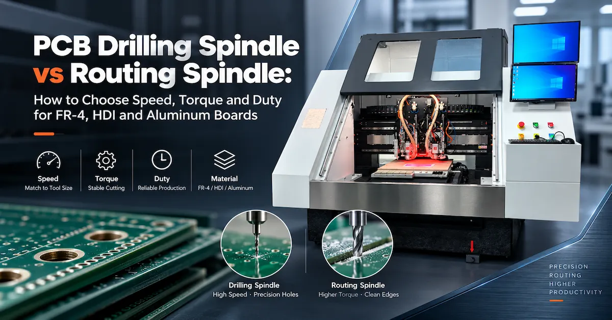




Choose tools around the hole, slot, or contour you must produce—not just a matching nominal diameter. Use this guide to review geometry, shank fit, process limits, supplier evidence, and accepted-board cost.
For PCB manufacturing engineers, drill and router procurement is a process-control decision. A low-price tool can become expensive if it creates oversize holes, chipped laminate edges, excessive breakage, or unplanned machine stoppages. Purchasing teams also need to distinguish between a machine's published tool-diameter range and the specification of a particular consumable.
This guide focuses on PCB drill bits / router bits selection and RFQ preparation. For deeper analysis of gradual router wear and replacement triggers, read CHIKIN CNC's PCB router-bit wear guide.

1. PCB Drill Bits vs Router Bits: What Actually Changes?
A PCB drill has a pointed cutting end designed to enter the laminate and generate a hole. Its process is dominated by axial motion, chip evacuation, hole registration, and the condition of the hole wall. A router uses cutting edges along its working length while moving through a contour; lateral forces, tool deflection, fixture rigidity, and edge finish are central.
| Selection factor | PCB drill bit | PCB router bit |
|---|---|---|
| Primary task | Through-holes, component holes, mounting holes, tooling holes | Board profiles, slots, internal windows, isolation of routed outlines |
| Main cutting motion | Axial penetration | Lateral path cutting |
| Geometry focus | Point, margins, flute evacuation, working length | Flute pattern, cutting length, tip form, chip removal |
| Typical process risk | Broken drill, hole-position error, smear, burrs | Rough edges, fiber pull-out, oversized slots, tool deflection |
| Useful tool-life unit | Qualified drill hits under a defined stack and material | Qualified routed distance under defined conditions |
| Buyer document | Hole chart plus drill/finished-hole requirements | Contour drawing plus slot, kerf and edge requirements |
They are not interchangeable simply because both can be held by a small CNC spindle. A pointed PCB drill should not be assigned a demanding contour-routing operation without explicit tool-maker approval. Likewise, a router bit must not be assumed suitable for producing precision plated-through holes.
2. Match Tooling to FR4, Multilayer and Other PCB Materials
Rigid FR4: Glass fibers change the cutting problem
FR4 combines resin with glass reinforcement. The reinforcement is abrasive, so the tool material, edge geometry, chip evacuation, and heat control all matter. Carbide is widely used in production PCB drilling and routing, but different grades and geometries can behave differently in the same laminate.
For drills, review the finished-hole requirement, laminate thickness, stack height, copper distribution, and approved entry/backup material. For routers, identify the required outline, the minimum slot width, panel support, and the length of cut per panel.
Multilayer boards: Do not confuse drill diameter with finished hole size
A fabrication drawing may specify a finished plated-hole diameter. The mechanical drilling diameter can differ because copper plating changes the final opening. That allowance depends on the fabrication process; do not apply one universal increase to every job. Request confirmation from the PCB process engineer before ordering the drill size.
Small mechanical drills also have limits related to working length, runout, material thickness, and stack conditions. Laser-created microvias are a separate process and should not be presented as a normal capability of every mechanical drill.
Aluminum-based, high-Tg and rigid-flex constructions
These materials should be assessed individually. A router proven on standard FR4 may require another geometry or process window for metal-core board profiling. Rigid-flex panels introduce support and material-transition concerns. Ask tooling suppliers for application-specific recommendations supported by trial results, rather than assuming one universal bit family covers every board.
3. Eight Specifications to Confirm Before Buying PCB Drill Bits or Router Bits
Confirm the actual required hole or routed slot size, tolerances, and how the tool diameter is inspected.
Match the holder or collet specification; a cutting diameter is not necessarily the shank diameter.
Consider board thickness, stack, entry/backup materials, and a safe, qualified engagement length.
Specify drill-point and flute geometry or the router's flute style and tip configuration.
Request carbide grade, surface treatment or coating only where supported by the tool supplier.
Confirm the spindle, collet, insertion and measurement method, not merely the bit's nominal size.
Document approved speed, feed, stack height or depth, extraction and tool-path strategy.
Request manufacturer part number, drawing revision, lot identification and inspection evidence.
A common purchasing error is ordering a tool based on “3.175 mm” without establishing whether that dimension describes its cutting diameter or shank. Another is buying the correct diameter with insufficient cutting length or an incompatible tip.
The related PCB spindle-collet inspection guide explains why cleanliness, insertion, concentricity, and holder condition must be considered alongside tool quality.
4. Router Geometry: Diamond-Cut, Chip-Breaker or Another Flute?
PCB router bits may use diamond-pattern cutting edges, chip-breaker forms, or other flute geometries. Each design changes how the tool engages the laminate and moves material away from the cut. There is no defensible single “best” geometry for all PCB routing jobs.
- Diamond-cut or diamond-pattern router: Often evaluated for fiberglass laminate routing where controlled edge cutting and particle removal are priorities. Actual results depend on tool design and process conditions.
- Chip-breaker geometry: Uses interrupted cutting features intended to manage material removal. Suitability depends on the laminate, slot, routing depth and the supplier's recommended cutting window.
- Other end-mill profiles: May be relevant to particular materials or contours, but a conventional metalworking end mill should not be presumed to match a dedicated PCB router.
For small slots and internal features, determine the minimum permissible tool diameter from the engineering drawing. For a routed outline, compare edge quality, dimension, tool loading, and dust handling across qualified tool types. Trial the alternatives using the same board, fixture, spindle and inspection standard.
5. Confirm Machine and Collet Compatibility Before the RFQ
CHIKIN CNC publishes drilling and combined drilling/routing machines with different spindle configurations. The following are published equipment tool-diameter ranges, not a guarantee that any particular third-party bit, shank, tool length or coating is automatically compatible.
| CHIKIN equipment reference | Published tool-diameter information | Relevant decision |
|---|---|---|
| CK-02D: 2-spindle drilling machine | Drilling: 0.15–6.35 mm | Check high-speed drilling tool, shank/holder and actual stack requirements. |
| CK-04D: 4-spindle drilling machine | Drilling: 0.15–6.35 mm | Control tool lot and qualified hit limits across multiple heads. |
| 1 Drill + 1 Route with CCD | Drilling: 0.15–6.35 mm; routing: 0.5–3.175 mm | Specify drill and router tools independently, including their holders. |
| CK-04R: 4-spindle drilling/routing machine | Confirm actual tool interface for the ordered configuration | Verify routing geometry, cutter length, magazine fit and tool checks. |
The website also lists a CHK 3.175 collet in its related parts offering. Its shank dimension must not be taken as proof of compatibility with every CHIKIN spindle; confirm taper, length, retention and spindle model against the installed machine.
Relevant CHIKIN configurations describe automatic tool changing and tool length, diameter or broken-tool detection. These are valuable setup controls, but broken-tool detection is not the same as measuring gradual edge wear. Ask which functions are included with the exact model and whether they apply to the selected tools.
Need to Match Tooling to a PCB CNC Machine?
Send your machine model, spindle and holder identification, PCB material, drill/hole chart, routing path and production targets. Ask the CHIKIN team to review the tooling interface and suitable equipment configuration.
6. Set Feed, Speed and Tool Life from Qualified Trials
Machine maximum RPM is not a ready-to-use cutting recipe. The working speed and feed depend on tool diameter, geometry, material, board stack, spindle condition, and the tool manufacturer's recommendations.
Two relationships can help engineers review technical proposals:
- Drilling feed (mm/min) = spindle speed (rev/min) × feed per revolution (mm/rev).
- Routing feed (mm/min) = spindle speed (rev/min) × number of cutting teeth × chip load (mm/tooth).
These formulas describe geometry-based relationships, not universally safe settings. Some PCB routing geometries do not map neatly to an ordinary end-mill tooth-count model, so use the geometry-specific process recommendation instead of inserting a guessed chip load.
Evaluate drills by qualified hit count for a clearly defined material and stack. Evaluate router bits by cumulative routing distance and accepted edge quality, with panel count retained as an additional reference. The limits should come from repeated production trials—not generic claims of “10,000 holes” or “long-life carbide.”
7. Diagnose Defects Before Blaming the Cutting Tool
| Observed defect | Possible tooling relationship | Other conditions to check |
|---|---|---|
| Drill breaks unexpectedly | Excessive slenderness, tool damage or unsuitable geometry | Runout, stack height, feed, entry material, clamping |
| Oversize or inconsistent holes | Tool runout or diameter issue | Spindle/collet condition, drill wander, measurement method |
| Hole-wall smear or burrs | Incorrect geometry or dull cutting edge | Heat, feed/speed, laminate, backup material |
| Rough routed edges | Unsuitable flute or wear | Panel vibration, route direction, dust extraction, support |
| Slot width drifts | Tool deflection or effective diameter change | Runout, path compensation, cutting load, fixture |
Change one controlled variable at a time. A fresh tool that immediately produces the same defect should trigger checks of the spindle, collet, fixture and extraction, not another expensive tooling order. CHIKIN's drilling-versus-routing spindle explanation provides useful background on why axial and lateral tooling impose different spindle demands.
8. Buy for Cost per Accepted Board, Not Unit Price Alone
Tool price does not describe manufacturing cost. A low-cost drill may need frequent replacement; a router may cut for a long time but fail the edge-quality requirement before it physically breaks.
Drill tooling cost per accepted hole = relevant drill spend ÷ accepted holes produced. Router tooling cost per accepted board = relevant routing-tool spend ÷ accepted boards routed. These measures should be reviewed alongside tool-change labor, scrap, downtime and inspection cost.
Ask tooling vendors to report the test material, diameter, stack or routed path, machining conditions, sample size and withdrawal criterion. Without those variables, tool-life promises from different suppliers cannot be compared fairly.
9. PCB Drill Bit / Router Bit RFQ Checklist
Use the following purchasing brief when evaluating tooling, CNC compatibility, or an equipment-and-consumables package.
| Send to supplier | Minimum information |
|---|---|
| Application | Hole drilling, plated-hole drilling allowance, slot or profile routing |
| PCB construction | Material, layers, thickness, high-Tg/metal-core/rigid-flex if applicable |
| Drawing | Hole chart, finished-hole requirements, contour/slot and tolerances |
| Tool details | Cutting diameter, shank, point/flute form, cutting length and overall length |
| Machine interface | Machine model, spindle ID, collet/holder reference, tool magazine limits |
| Production conditions | Spindle RPM, feed, stack, route length, tool path, extraction and fixture |
| Qualification | Inspection method, sample quantity, acceptance criteria, observed defects |
| Commercial requirements | Expected monthly consumption, lot traceability, lead time and repeat orders |
Request a drawing or datasheet for the exact tool and a sample-trial plan where practical. If ordering a CHIKIN machine, ask for the approved holder/tool specification as part of equipment acceptance documentation. A machine's published diameter range alone is not a substitute.
10. Frequently Asked Questions
Can PCB drill bits be used as router bits?
Not as a general substitute. Drill-point geometry is optimized for axial hole-making, whereas router geometry is intended for lateral contour cutting. Use only processes explicitly supported by the tool and equipment manufacturer.
Are carbide PCB drill bits better than ordinary HSS tools?
Carbide is widely used for abrasive PCB laminates and high-speed precision applications. However, a selection must still account for brittleness, machine runout, geometry, material and validated tool life; material alone does not determine a safe process.
Is a 3.175 mm router shank compatible with every PCB routing spindle?
No. The collet bore is only one dimension. Holder design, retention, tool length, balance and spindle-specific limitations must all be verified.
How should PCB factories compare tool life?
For drilling, compare qualified hits under the same material, stack and parameters. For routing, compare qualified routed distance and accepted edge quality. Include scrap, replacement time and tool-lot traceability.
Does CHIKIN CNC sell every drill bit and router bit described in this guide?
The verified website pages primarily document PCB drilling/routing machines, related parts and tooling discussions. Availability of specific drill or router consumable SKUs should be confirmed directly through CHIKIN's inquiry team rather than assumed from this guide.
Request an Application-Based Equipment & Tooling Review
Share your board drawing, tool dimensions, current defect or wear issue, machine model and required output. Ask for a model-specific compatibility review and quotation scope.
Conclusion
Choosing PCB drill bits and router bits starts with the finished feature: precise holes need qualified drill geometry, while clean slots and board outlines need suitable routing geometry and controlled lateral cutting. Diameter, shank, working length, material, collet fit and documented process conditions matter more than a generic “carbide bit” label.
For new equipment or tooling changes, use a consistent RFQ and representative board trials to verify accepted output and operating cost. Review CHIKIN CNC's drilling and routing equipment and contact the technical team with your application specifications before committing to a particular configuration.