




A router bit breaks earlier than expected. The operator replaces it, and the next board still has a rough edge. Or a small drill produces a few oversize holes even though the program, stack height, and tool supplier have not changed. It is tempting to call the cutter defective. Before changing the feed or blaming the bearings, look at the interface that grips the tool. One fiber, a ring of resin, or a nick in a collet can change how a small shank is held.
This is the everyday reason to take pcb spindle collet cleaning seriously. On the bench, the useful question is whether a deposit was holding one segment open or whether the part itself has lost its grip. Photograph the deposit before removing it, then repeat the same runout measurement with the same reference shank. If nothing changes, look beyond the collet: a bent shaft, tired bearing, moving panel, or unsuitable cutter will not become sound because the bore is clean.
The procedure below is deliberately system-aware. PCB machines use different gripping arrangements: a removable spring collet and nut, an automatic-tool-change cartridge, a direct-grip mechanism, or a supplier-specific high-speed assembly. Not every spindle uses an ER collet. On one drilling head the clamp may be removable while the air-bearing assembly is sealed; a routing head alongside it may use a separate nut and wrench. Write down both spindle models before reaching for solvent or a service tool. This guide gives the inspection order, while the model manual supplies the permitted removal method and limits.

Quick Answer: What Should a Technician Do First?
Stop the machine safely, record the tool and job, and inspect the shank before disturbing the setup. Remove the collet only by the maker's method. Clean accessible mating surfaces with approved materials, inspect under good light, install a verified tool at the documented stick-out, and measure runout at a repeatable gauge point. If a clean, correctly assembled collet still slips or fails the documented limit, compare with a known-good replacement. If the reading remains high, investigate the holder, taper, shaft, and bearings rather than repeatedly replacing collets.
The diagnostic order matters. Cleaning a dirty part before photographing a slippage mark destroys useful evidence. Changing the collet, bit, spindle speed, and fixture all at once makes a good-looking test board hard to interpret. Keep the process controlled so the next shift knows what actually solved the problem.
1. Why a Small Collet Error Has a Large PCB Effect
A collet holds the cylindrical shank close to the spindle axis. Its spring slots allow the clamping surface to close around the shank when the matched holder or actuator applies force. A compacted fiber at one slot leaves a tiny gap on that side of the bore; a short shank insertion gives the remaining contact less area to grip. Either fault can make a new, sharp cutter trace a wider path than the program calls for.
The effect is especially visible with small PCB drills. A tiny radial error is a meaningful fraction of a micro-drill's diameter. One cutting lip may carry more work than the other, while hole size, wall condition, and drill life change. During routing, eccentricity makes one flute take a heavier chip; the other may rub. The operator may see repeating wall marks, burrs, heat discoloration, or frequent bit changes. Those outcomes can also come from feed, extraction, and fixture support, so use the collet check as part of a wider process investigation.
CHIKIN's public guide to rough PCB routed edges specifically lists dirty collet surfaces, the wrong collet size, excessive tightening, and holder damage among possible runout contributors. Its drilling and routing equipment pages also describe tool detection and automatic tool changing on selected models. These features support process control; they do not tell you that every model has the same collet or service procedure. Ask for the spindle-specific drawing with the machine quotation.
2. Identify the Holder Before Choosing a Cleaning Method
Start at the two nameplates, not at an online photograph. Put the machine serial number and spindle model on the work order, followed by the collet marking, bore, taper, nut or drawbar interface, and revision. Photograph the nose before taking it apart and place the removed part beside its label. An illegible mark is a reason to consult the original bill of materials, not a reason to guess from the number of slots.
An ER-style assembly may have a collet captured in a nut before installation. A proprietary PCB drill collet may use a different retention arrangement and require a service tool. A collet in a high-speed spindle may be matched to a balanced rotating assembly. The correct steps for one type can damage the other. Do not pry a collet out with a screwdriver, hammer it free, or substitute a familiar nut because the threads seem to fit.
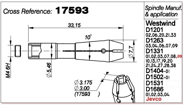
CHIKIN lists a CHK 3.175 collet and a 17593 spindle-collet spare part on its public site. Those listings help buyers start a fit conversation, but their pages caution that appearance alone does not establish the exact standard or compatibility. A 3.175 mm shank dimension does not prove the outer taper, overall length, slot geometry, or actuator is correct. Match the installed part and ask CHIKIN to confirm against the spindle model before purchase.
3. Make the Machine Safe and Preserve the Evidence
Follow the plant's lockout and spindle-service procedure. Stop rotation, isolate the energy sources required by the machine manual, and wait for the tool and spindle to stop completely. A quiet spindle does not mean a quiet tool changer: an axis or pneumatic drawbar can still move. The technician must account for stored air, hydraulic pressure, and electrical energy under the site's procedure before opening the nose. Leave ATC and spindle internals to personnel trained for that model.
Record the machine number, head position, spindle model, hours if available, tool ID, shank diameter, holder part, program revision, board material, shift, and observed defect. Save a sample panel and photograph the tool shank before cleaning. A polished band, axial scratch, or dark fretting mark may indicate slip or poor contact. A broken bit alone does not establish the cause; record when and where it failed.
Lay out a clean, covered tray for the removed parts. Keep each head's collet, nut, spring, spacer, and tool separate. Do not mix components from several heads to save time. A misplaced nut or a slightly different revision may create a new runout problem that did not exist before the inspection.
4. Remove and Clean the Collet in a Controlled Sequence
Release the tool using the specified actuator or wrench. Support it so a sharp drill cannot drop onto the table or break inside the nose. Remove the collet and associated nut only if the service instructions allow operator removal. If the unit is a sealed cartridge or the manual requires factory service, stop there and arrange the authorized procedure. Never disassemble a high-speed spindle's bearing stack as part of routine collet cleaning.
First remove loose PCB dust with the approved vacuum or a soft, non-shedding brush. Use a lint-free wipe for the tool shank and accessible seating faces. Check the service sheet before wet cleaning: it should name the liquid, the surfaces it may touch, and whether the grip must be dry at assembly. Give any approved cleaner time to evaporate. A general-purpose aerosol or penetrating oil may wet a seal, change the friction at the bore, or leave a film that catches the next load of dust. Never flood the spindle nose.
Pay attention to the slit openings and the internal bore. Resin and fiberglass can pack into a slot, preventing even compression. Clean the mating taper and nut or actuator contact face only in the way specified for that design. Do not scrape the precision taper with a steel pick or polish away a stain with abrasive paper. Material removal changes geometry. If a deposit cannot be removed without force, photograph it and ask the supplier how to proceed.
Do not aim the shop air gun into a spindle nose. Unless the service sheet specifies a pressure and direction, that jet may move fiberglass into the seal rather than out of the machine. Check a built-in purge-air supply at its specified point; it is not a substitute for blowing into the clamp. Under a lamp, the bore and slots should show no remaining particles or wipe fibers.
5. Inspect for Spindle Collet Wear, Damage, and Poor Grip
Inspect the collet under bright, even light and magnification suitable for the part. Look along each slot for a crack extending from an end or a sharp corner. Look at the bore for scoring, a shiny one-sided contact patch, a raised burr, corrosion, embedded particles, or a change in surface texture. Inspect the outer taper, rear engagement surface, nut, and threads for galling or uneven contact. This is the practical meaning of spindle collet wear inspection, not merely checking whether a part still looks shiny. Use the manufacturer's wear criteria when available; a photograph of a new part is only a comparison aid.
Check the tool shank as well. A worn collet may leave repeatable slip marks, but an undersize, scratched, oily, or noncylindrical shank can produce the same symptom. Verify that the shank is the intended diameter for that exact collet. Do not clamp across a transition, a flute, or an unapproved portion of the tool. Maintain the specified minimum insertion and stick-out; a very long exposed tool magnifies deflection and can make a sound collet appear defective.
Visible cracks, distorted slots, damaged threads, a burred taper, or a tool that can be pulled or rotates when it should be secure are reasons to stop using the assembly pending the maker's guidance. Do not bend the segments back, grind the bore, or use extra torque to mask poor grip. That approach may postpone a slip for one job and damage the spindle on the next.
6. Measure Spindle Collet Runout Without Confusing the Sources
The term spindle collet runout describes a system measurement, not a certificate that the collet alone is good or bad. It combines the spindle axis, nose or taper, collet, nut or actuator, tool shank, insertion, and gauge setup. Measure a clean, known-good reference shank or test bar at the defined distance from the collet face. A dial indicator reading at the tip of a long cutter cannot be compared fairly with a short reference pin near the nose.
Follow the spindle maker's static measurement method. Use a calibrated indicator with suitable resolution, mount it rigidly, and rotate the assembly by hand only when the manual permits. Never touch a spinning tool with an indicator. Record total indicated runout, gauge location, reference diameter, insertion depth, and orientation. Repeat the measurement after reseating the same reference part. If a tool is itself bent, the reading may change when the tool is rotated relative to the collet.
Measure at two points if the service procedure permits: near the holder and at the specified projection. A larger change with distance can reveal an angled seating error or bent shank. If a clean replacement collet reduces the reading under identical conditions, the removed collet is implicated. If both collets give a similar high reading, inspect the nut, holder taper, spindle shaft, and bearing condition. Do not infer a bearing failure from the tool-tip reading alone.
Avoid publishing a universal micrometer limit. The acceptable figure depends on the tool diameter, gauge point, spindle specification, and process tolerance. The spindle supplier's acceptance sheet and a qualified reference coupon should define your alert and stop limits. A reading can satisfy a broad holder specification yet still be unacceptable for a very small PCB drill.
7. Clean, Reuse, or Replace: A Decision Table
| Finding after cleaning | Immediate action | Evidence to record | Release condition |
|---|---|---|---|
| Light removable dust; no damage; runout within documented limit | Reassemble and test | Before/after photos, gauge reading, tool ID | Reference coupon and retention check pass |
| Resin deposit in a slit; no visible crack | Use approved cleaning method, then remeasure | Deposit location, cleaning method, repeat reading | Stable grip and acceptable runout after repeat installation |
| One-sided polish or slip marks | Check shank size, insertion, actuator force, and taper | Tool marks, dimensions, clamping setting | Root cause corrected and coupon passed |
| Crack, bent segment, burr, corrosion pit, or damaged thread | Remove from service; replace compatible part | Part number, photographs, failure history | Approved replacement installed and verified |
| High runout with two clean, verified collets | Escalate beyond the collet | Gauge method, two part IDs, readings | Spindle/holder investigation completed |
| Runout acceptable but board edge still rough | Continue process diagnosis | Cutter, fixture, feed, extraction, board material | Production sample meets quality criteria |
This table is a triage tool. It does not replace the machine's defect limits. Record the decision so a later shift does not reinstall a rejected collet because it looks clean after storage.
8. PCB Machine Collet Replacement: Fit Matters More Than Appearance
Order by the original part number and the exact spindle or holder revision whenever possible. Confirm inner gripping diameter or range, outer taper and length, rear engagement feature, slot configuration, nut or actuator compatibility, balance or speed rating if specified, and any supplier-matched components. Check whether a nut, spring, seal, or tool-change cartridge must be replaced together with the collet. A similar photograph cannot answer these questions.
For pcb machine collet replacement, a useful RFQ starts with the machine and spindle nameplates, then shows the removed part marking beside a scale and includes the original order number or drawing. Add a note if the tool hit a fixture; a collision can mark the spindle nose as well as the collet. Have the supplier identify the exact proposed part, state whether it is original or equivalent, and specify how fit and runout will be checked on receipt.
At the bench, put the old and new collets next to the drawing. Compare the marking, overall length, rear engagement, nose profile, and slot pattern before either goes near the spindle. Keep the new part's packaging and certificate with the job card. If one feature disagrees, quarantine the part for clarification; trying it in a costly spindle is a poor way to discover the difference.
Assembly order is design-specific. For an ER-style holder, the collet may need to engage the nut correctly before the nut is mounted; for another spindle, that instruction may not apply at all. Put the wrench and torque setting from this holder's manual on the job card so the next technician can repeat the installation. An empty collet and a length of pipe on the wrench are not a retention test. Unless the maker prescribes otherwise, do not tighten without the specified tool shank or use extra leverage to hide a worn grip.
9. Verify Retention, Runout, and the First PCB Sample
After assembly, confirm that the tool-change actuator reports the expected state and that the tool is retained according to the approved method. Keep hands away from the rotating path. Check for interference between the tool, pressure foot, fixture, and workpiece at the programmed stick-out. A replacement collet can change seating position enough to require tool-length calibration even when it is nominally the same part.
Measure static runout at the same point and with the same reference shank used for the pre-change reading. Perform the maker's permitted low-speed and normal-speed checks, watching for alarms, unexpected noise, vibration, or temperature rise. Do not immediately release a full batch on the basis of a smooth no-load spin. Run a representative coupon with the actual drill or router geometry and board stack.
For drilling, inspect hole diameter, position, burrs, entry/exit condition, and tool wear over a useful sample. For routing, compare edge finish, wall marks, dimensional accuracy, burrs, and whether the cutter stays at its intended position. Save the coupon and record the acceptance criteria. If the reading improves but the board does not, investigate feeds, fixturing, extraction, tool geometry, and program alignment before ordering more collets.
Release the machine only after the maintenance lead or designated quality owner signs the result. The record should include the old and new part IDs, reason for change, method, gauge result, test-board result, and date. This creates a baseline for the next cleaning cycle.
10. A Practical Collet Maintenance Schedule
| When | Check | Record | Escalate when |
|---|---|---|---|
| Each tool change | Inspect shank and exposed gripping area; confirm seating | Tool ID, abnormal marks | Tool slips or a chip is trapped |
| Each shift | Listen for changed cutting sound and check board defects | Head, job, defect location | Defect repeats with a verified cutter |
| Planned cleaning | Remove and clean only as the manual permits | Part ID, method, photographs | Deposit persists or a slot is damaged |
| Periodic measurement | Check runout with reference shank and gauge point | TIR, point, tool projection, temperature | Trend or documented process limit is exceeded |
| After a crash or broken tool | Inspect collet, holder, taper, and spindle nose | Incident, photos, test results | Visible damage or high runout remains |
| After replacement | Check retention, runout, and a representative coupon | New part ID, acceptance sign-off | Any test fails |
Do not turn this table into an arbitrary fixed interval. A high-mix prototype shop may perform many manual changes; a four-head production machine may accumulate hours quickly under a stable recipe. Dust, laminate type, extraction, tool size, shifts, and crash history all change the burden. Set the frequency from the maker's requirements and your own trend. CHIKIN includes holder cleaning in its discussion of collet maintenance. HAIMER's published tool-holder overview also identifies collet checking and cleaning as normal care for mechanical collet chucks, while its product-specific values cannot simply be transferred to a PCB spindle.
11. Common Mistakes That Create a Second Problem
The first mistake is blowing dust into the nose with unrestricted compressed air. The second is using abrasive paper to make a precision taper look bright. Both can make a superficially clean assembly less accurate. A third is spraying oil onto the gripping bore without checking the manual; some systems need a dry contact surface, and excess lubricant can alter retention or collect debris.
Another mistake is assuming that any collet marked with the correct shank size will fit. The bore is only one dimension. A mismatched taper, length, nut, or retention feature can clamp unevenly or fail to release. Mixing a worn nut with a new collet can also hide the source of a runout change. Treat the holder as an assembly, but change and document one variable at a time during diagnosis.
Finally, do not use the tool itself as a cleaning implement. Turning a sharp carbide shank against a contaminated bore can score both. Do not measure runout at an arbitrary location and compare the result with a catalog number taken at a different projection. And do not approve a collet replacement solely because the spindle sounds quieter: the final answer is the measured assembly and accepted PCB sample.
12. How to Separate Collet Problems from Other Machine Faults
If a defect follows one cutter between heads, suspect the cutter or its shank. If it remains on one spindle with two verified cutters and collets, investigate the nose, actuator, bearings, speed control, or motion system. If it appears only on one panel position, inspect the fixture and board support. If it appears after a filter fills, check extraction before condemning the collet. A good diagnosis tracks which variable the defect follows.
In a drilling station, look at the hole pattern as well as isolated holes. An incorrect drill diameter creates a consistent size error; a poorly held drill may produce scatter, breakage, or wear that accelerates over the run. In routing, compare straight sections, corners, and slots. When the rough edge appears only across a gap in the fixture, test panel support before replacing the clamp. When it appears at the same spindle speed on well-supported panels, capture a vibration trace and compare it with the baseline.
If the spindle has recently been repaired or crashed, take a separate shaft or nose reading under the approved service method. A new collet cannot make a damaged taper concentric. Conversely, a clean collet that fixes the problem should not trigger an unnecessary bearing replacement. CHIKIN's PCB router-bit wear guide recommends a reference tool, clean holder, runout check, and representative sample before attributing every rough edge to cutter life.
13. Procurement Checklist for a Spare-Collet Package
The purchase request should name the equipment and the verification work, not just a part description. Include:
- Machine model and serial number, spindle maker and model, head position, and holder or ATC revision.
- Original collet marking and photo, bore size, tool-shank tolerance, outer geometry, and any available drawing.
- Nut, actuator, spring, seal, or cartridge parts that must remain a matched assembly.
- Approved cleaning materials, service tool, tightening method, and torque information from the correct manual.
- Required spare quantity by head, lead time, packaging, and traceability to an ordered part number.
- Runout acceptance point and method, retention check, and production-coupon criteria.
- Who performs installation, who approves restart, and what support is available if the test fails.
For a multi-spindle machine, confirm whether every head uses the same part and revision. Identical-looking housings can hide a different spindle or retrofit. If a factory is buying a new drilling-and-routing platform, ask the supplier to include consumable collets and holder service requirements in the quotation. A spare that can be identified and installed correctly is worth more than a vague promise of fast parts support.
CHIKIN offers PCB drilling and routing machine configurations with multiple heads and tool-management features on selected models. The public pages are useful starting points for application discussion, but the final collet design and maintenance limits belong in the machine-specific documentation. Request a sample test with the intended board, tool diameters, and quality criteria before treating a configuration as approved.
14. Questions from the Maintenance Bench
The collet is still installed. What can I clean safely?
Only the accessible surfaces, and only if the manual permits that method. Dust trapped inside slots or behind a nut may require authorized removal. Do not push debris deeper into the spindle with a brush or air jet. If the collet is part of a sealed cartridge, follow its service process.
Does cleaning always restore spindle collet runout?
No. It can remove contamination that prevents proper seating. It cannot repair a cracked segment, distorted taper, bent tool, damaged holder, or spindle shaft problem. Measure before and after with the same reference and gauge point.
The bore is clean. Which defects still mean retirement?
Do not put a cracked slot or bent segment back into production. The same applies to damaged threads, a taper with a raised burr, grip that slips with a verified shank, or runout that still exceeds the documented limit after reseating. Photograph the defect and compare it with the maker's reject criteria before the old part goes into the scrap bin.
Both tool shanks are 3.175 mm. Are their collets interchangeable?
No. The shank size does not identify the outside geometry, engagement, nut, balance, or compatible spindle. Match the precise part to the machine and ask for written fit confirmation when the original number is uncertain.
Should I tighten a slipping tool harder?
No. Mark the present shank's grip depth and verify its diameter and surface, then inspect dirt, wear, and actuator setting. More force may crush an already distorted collet or bruise the holder; it does not prove the cutting axis is centered.
The part number is unreadable. What should the supplier receive?
Send the machine and spindle identifiers, the removed collet's marking, photos, dimensions from the approved drawing, the tool-shank size, the failure symptom, and the runout measurements made with a known reference. These details reduce the risk of a visually similar but incompatible substitute.
Conclusion: Verify the Complete Tool-Holding System
The useful maintenance cycle is simple in concept: preserve evidence, make the machine safe, identify the holder, clean only by the specified method, inspect every gripping surface, and measure the assembled system under a repeatable setup. Replace a damaged or incompatible collet, then prove the result with a reference tool and actual PCB sample. A clean appearance is not the acceptance test; stable retention, measured runout, and board quality are.
For a quote or a service review, share the spindle model, current collet marking, tool sizes, board material and thickness, a photograph of the defect, and the measurement record. That gives CHIKIN a useful starting point to discuss a compatible replacement or a machine configuration without guessing from a nominal bore diameter.
Request a PCB Spindle Collet Fit and Maintenance Review
If the new part does not restore the edge or hole, send the before-and-after readings with the reference tool, holder, and fixture identified. Those paired results show whether the fault stayed with the spindle, moved with the tool, or appeared only in a particular board setup.