



Production teams often notice spindle bearing trouble through a small change that is easy to explain away. A familiar cutting sound becomes sharper. The housing feels warmer after the same job. A router edge shows more burrs even though the cutter is new. A hole gauge starts to drift, or the machine leaves a faint pattern on an otherwise stable contour. None of those clues proves that a bearing is worn. Together, however, they are a reason to stop treating the spindle as a black box.
The phrase pcb spindle bearing wear covers a family of failure modes: raceway fatigue, ball or roller damage, loss of preload, lubricant breakdown, contamination, seal wear, and damage caused by an impact or an incorrect tool change. High-speed PCB spindles are especially sensitive because a small amount of runout or imbalance is amplified at high rotational speed. A bearing can still turn while the process has already moved outside its qualified window.
This guide is written for engineers, maintenance leaders, and buyers who need a defensible next step. It explains what noise, heat, vibration, and runout can tell you; what they cannot tell you alone; and how to separate a spindle problem from a dull tool, dirty collet, poor fixturing, or an incorrect cutting program. The recommendations are diagnostic practices, not a promise that every machine or bearing follows the same limit. Use the machine maker's manual and the spindle supplier's acceptance values whenever they are available.

Quick Answer: What Are the Four Warning Signs?
The four most useful warning signs are a new or changing sound, a repeatable temperature rise, vibration that appears at a specific speed or load, and measurable runout at the tool holder or test bar. Noise is an early clue, heat shows that losses are accumulating, vibration reveals an unstable rotating system, and runout shows how far the tool axis is moving from the intended path. A single symptom can come from tooling or setup. Two or more symptoms that move together deserve a controlled inspection before the next long batch.
Do not diagnose by touching the spindle housing after a job. Human touch is not a calibrated measurement, and a warm housing may be normal for one cooling arrangement and abnormal for another. Record the same points at the same time in the cycle: ambient temperature, idle temperature, loaded temperature, RPM, tool diameter, material stack, feed, and extraction condition. Trend data is more useful than a one-off impression.
1. Why PCB Spindles Make Bearing Wear Hard to Spot
PCB drilling and routing machines combine small tools, fast rotation, thin workpieces, and demanding registration. A drill may be only a fraction of a millimeter in diameter, while a routing tool may experience continuous side load in an outline or slot. The spindle bearing system must keep the tool centered under both conditions. A bearing can have enough remaining life to complete a light prototype job but not enough stiffness for a high-volume panel run.
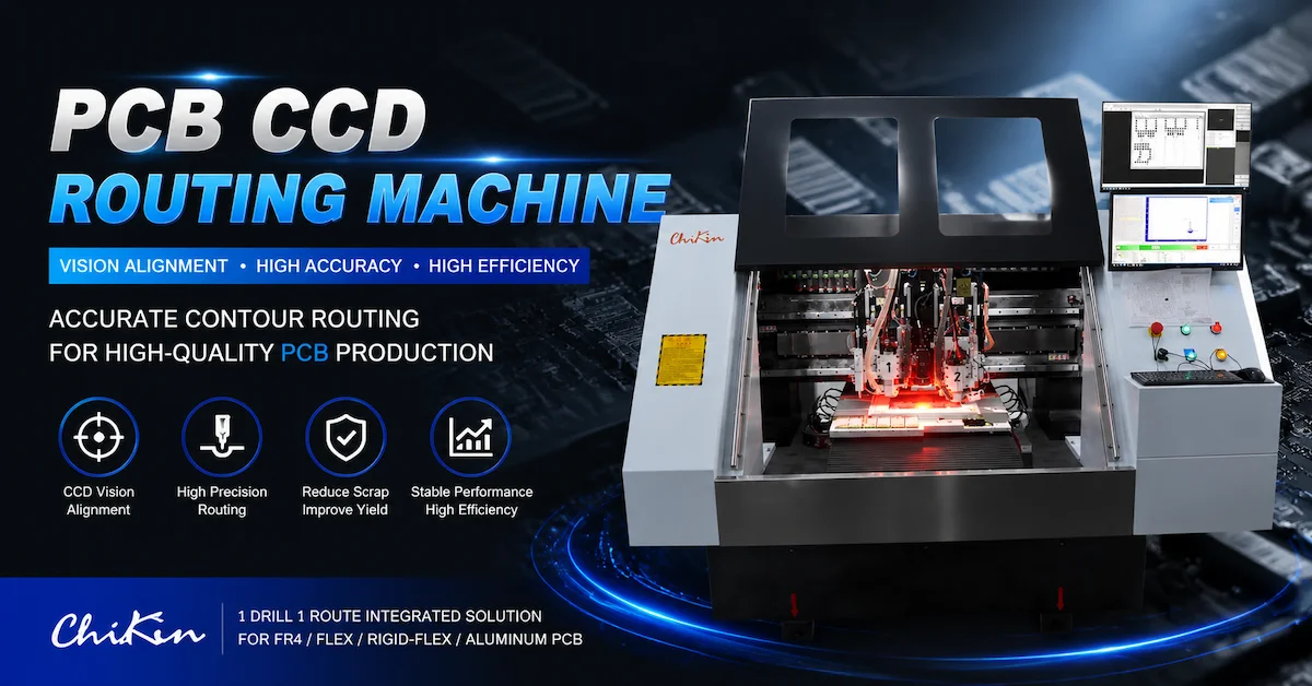
The machine structure also affects what the operator hears and measures. CHIKIN's public product information describes features such as granite bases, linear guides, ballscrews, automatic tool change, tool detection, and CCD alignment on selected PCB platforms. Those features can improve the overall process, but they do not remove the need to monitor the rotating assembly. A rigid frame may make a worn bearing easier to identify because fewer other parts are moving at the same time.
The first useful question is therefore not, "Is the spindle old?" It is, "What changed under the same recipe?" Compare a known-good tool, a known-good board stack, and a familiar program. If the symptom follows the spindle from one station to another, the spindle becomes more likely. If it follows the tool, collet, fixture, or program, the bearing may be innocent.
2. Spindle Bearing Noise: What to Listen For
Normal spindle sound is not silence. Air-bearing systems, water pumps, cooling fans, tool engagement, and extraction equipment all contribute background noise. The useful signal is a change from the established sound at a defined speed and load. An experienced operator may describe a worn bearing as a growl, hiss, rumble, scrape, or repeating tick. Those descriptions are valuable observations, but they should be attached to RPM and operating conditions.
High-frequency whine can point to aerodynamic or electrical behavior rather than a bearing. A rough low-frequency rumble that grows with speed is more suspicious, especially if it remains when the tool is removed and the spindle is run under the manufacturer's permitted test condition. A click once per revolution can be caused by a damaged bearing element, a tool shank mark, a collet, or debris on the taper. The sound alone cannot identify the part.
For a practical check, record a short audio sample at idle, at two intermediate speeds, and at the normal production speed. Keep the phone or sensor in the same location and avoid placing it against a vibrating panel. Repeat the recording with the tool removed only if the procedure is allowed by the spindle maker. Mark whether the sound appears during acceleration, steady speed, deceleration, or cutting. A symptom that appears only under side load deserves a different investigation from a sound that appears at idle.
The related search term spindle bearing noise is often used as if it describes one fault. In reality, noise is a screening clue. Use it to decide which measurement to take next, not as permission to replace a bearing without checking runout, temperature, and tool condition.
3. Spindle Overheating: Read the Trend, Not the Surface
Bearing friction, lubricant shear, seal drag, electrical losses, and heat conducted from the cutting zone all contribute to spindle temperature. A rise that stabilizes at a repeatable level may be normal. A rise that continues longer than usual, reaches a new plateau, or appears at a lower load can indicate a developing problem. Cooling flow restrictions and ambient temperature can create the same pattern, so confirm those first.
Measure temperature with a repeatable method. A non-contact infrared reading can be useful for a trend if the surface emissivity and measurement angle are kept consistent. A contact sensor or the spindle controller's internal value may be more comparable, but only if the sensor location and calibration are understood. Write down the time from start, RPM, job type, coolant or air status, and the temperature at the bearing housing or approved measurement point.
Spindle overheating is more concerning when it arrives with a new sound or a change in vibration. Heat by itself can be caused by an overloaded tool, blocked water lines, a failing fan, a high ambient temperature, or a speed outside the recommended continuous-duty range. Check filters, pumps, flow switches, and alarm history before assuming the bearing is damaged. Do not increase cooling flow beyond the spindle maker's specified range as a substitute for diagnosis; condensation and seal issues can create a second problem.
For PCB routing, compare the same contour at the start and end of a shift. If edge quality worsens as the spindle warms, record the first-pass temperature and the later-pass temperature. If the edge changes while the temperature remains stable, look at tool wear, chip evacuation, and fixture movement. A disciplined comparison prevents maintenance teams from replacing a bearing when the real issue is a loaded cutter or insufficient extraction.
4. Spindle Vibration Symptoms: Match the Pattern to the Cause
Vibration can be felt through the housing, heard as chatter, seen as a repeating edge mark, or captured by an accelerometer. The pattern matters more than the word vibration. Imbalance often produces a strong response at the rotational frequency and its harmonics. Misalignment, a bent tool, a damaged taper, looseness, and bearing defects create different signatures. A machine frame or fixture can also resonate at a speed that has nothing to do with bearing damage.
Common spindle vibration symptoms in PCB work include a rough wall in a drilled hole, a repeating scallop on a routed edge, a sudden increase in tool breakage, or a tool mark that repeats at a constant pitch. If the mark changes when the cutter is replaced, inspect the tool and holder first. If the mark remains with a balanced reference tool and follows the same RPM, the spindle or mounting system becomes more likely.
The safest test is a controlled run with no workpiece contact, followed by a light test cut in a stable coupon. Use the smallest test that can reveal the symptom. Record the speed at which vibration begins, whether it disappears above or below that speed, and whether the response changes with a different tool holder. Never run an unfamiliar spindle at a higher speed simply to make a vibration easier to hear. Stay within the documented operating envelope.
If a vibration sensor is available, keep the sensor location and mounting method consistent. A magnetic base, adhesive mount, or handheld probe will not produce identical readings. The purpose of a maintenance trend is comparison with the machine's own baseline, not an unsupported comparison with a number from another spindle.
5. Runout: The Measurement That Connects Bearings to Tool Quality
Runout is the radial movement of the rotating tool or test bar as it turns. In a PCB spindle, total indicated runout can include bearing clearance, shaft geometry, taper condition, collet error, tool shank error, and measurement technique. That is why a high reading does not automatically prove that the bearing is worn. It does show that the cutting axis is not rotating as precisely as the process expects.
Measure at more than one point. Check the spindle taper or approved test bar close to the nose, then check the tool or holder at the working length. A large difference between the two points can indicate tool or collet deflection rather than a bearing issue. Rotate the tool or collet in the holder and repeat the reading. If the high spot moves with the tool, inspect the tool. If it stays with the spindle, inspect the taper, shaft, and bearing system.
Use a calibrated dial indicator or a suitable electronic gauge with a known resolution. Keep the spindle stationary unless the procedure specifically calls for a dynamic measurement. Clean the taper with a lint-free material and the approved cleaning method. Even a small chip can change a runout reading and create a false diagnosis. Record gauge model, contact force if relevant, measurement location, and tool length.
The key production question is not whether runout is zero. It is whether the reading is inside the process window for the smallest drill and the most demanding route. A change of a few micrometers may matter greatly to a micro-drill and be less important to a larger roughing tool. Set internal alert and action limits from validated samples, machine documentation, and the customer's hole or edge requirements.
6. A Symptom Matrix for Maintenance Teams
| Observation | Possible Bearing Contribution | Other Common Causes | Next Check |
|---|---|---|---|
| New rumble at constant RPM | Raceway or rolling-element damage; preload change | Tool imbalance, taper contamination, motor drive noise | Run unloaded with reference holder; compare audio and vibration |
| Housing temperature rises faster | Friction, lubricant problem, bearing preload | Coolant restriction, fan failure, high ambient temperature | Verify flow, fan, alarm history, and temperature trend |
| Chatter on a routed edge | Bearing stiffness loss or speed instability | Dull cutter, long tool stick-out, loose fixture, wrong feed | Repeat with short balanced tool and stable coupon |
| Hole diameter or position drifts | Radial movement or thermal growth | Tool wear, board movement, Z calibration, program offset | Measure runout and drill a reference coupon |
| Repeating mark at one speed | Resonance or rotating defect | Frame mode, holder imbalance, damaged cutter | Sweep only inside approved speeds; test another holder |
| Tool breaks more often | Runout, vibration, or axial error | Excessive feed, poor chip evacuation, incorrect depth | Review tool data, collet cleanliness, and spindle trend |
This matrix is deliberately non-exclusive. It keeps the investigation open long enough to avoid a costly parts swap based on one observation. A bearing replacement should be supported by a repeatable symptom, a measurement outside the machine or process limit, or a qualified spindle service report.
7. Bearing Damage Mechanisms in PCB Drilling and Routing
Fatigue is the classic mechanism: repeated contact stress creates surface damage that grows into spalling or flaking. At high speed, small defects can produce a clear vibration signature before the operator sees a visible mark. Loss of preload can reduce stiffness and increase runout. Excessive preload can generate heat and accelerate lubricant breakdown. Both conditions can come from the bearing itself or from an incorrect service procedure.
Contamination is another frequent cause. PCB dust, glass-fiber debris, copper particles, moisture, and cleaning chemicals can reach a bearing through a damaged seal, an incorrect air purge, or poor housekeeping around a tool change. A clean extraction path and careful taper cleaning help, but they are not substitutes for the spindle's specified sealing and purge arrangement. Never direct compressed air into a spindle nose unless the manufacturer explicitly allows it.
Impact damage can occur when a tool crashes into a fixture, a board stack is clamped incorrectly, or a collet is tightened with a damaged wrench or incorrect torque. The spindle may continue to run and pass a casual sound check while its runout has changed. Record crashes and unusual tool changes in the maintenance log. That history can explain a sudden shift in the trend.
Electrical and thermal stress also matter. Repeated rapid acceleration, operation outside the continuous-duty speed range, or loss of cooling can create a heat cycle that shortens grease or oil life. For a production buyer, the relevant specification is not only maximum speed. Ask for the permitted duty cycle, cooling requirements, service interval, and the process conditions used for the spindle's runout and temperature acceptance test.
8. Separating CNC Spindle Bearing Failure from Tooling Problems
Tooling is the most common false lead in a spindle investigation because a damaged cutter can make a healthy spindle look unstable. Start with a known-good reference tool and a clean, verified holder. Check the shank for scoring and the cutting edges for chipped carbide. Inspect the collet for dark marks, raised material, or contamination. Confirm that the tool length and diameter have been measured in the same way as before.
Next, repeat a short cut in a stable coupon. Use the same program, board support, feed, speed, and extraction setting. If the defect disappears with the reference tool, replace the tool or holder and continue monitoring before opening the spindle. If the defect remains, swap only one additional variable at a time. A second spindle station, if available, is useful as a comparison, but only when its tool, holder, and program are controlled as well.
The term cnc spindle bearing failure should be reserved for a confirmed condition, not an early hunch. Maintenance records are easier to defend when they say, "runout increased at the spindle nose with two verified holders and the temperature trend rose 12 degrees during the same recipe," rather than, "bearing failure suspected because the edge looked rough."
9. A Controlled Diagnostic Sequence
Use the following sequence when a symptom appears during a production shift:
- Pause the affected recipe and label the panel, tool, holder, and spindle station. Preserve the evidence before cleaning everything.
- Check immediate safety conditions: alarms, abnormal heat, smoke, coolant or air loss, loose parts, and signs of a crash. Stop the spindle if continuing could cause damage.
- Record the symptom with time, RPM, tool, material stack, feed, depth, and program revision. Save the controller alarm or maintenance log entry.
- Inspect the cutter, collet, taper, pressure foot, fixture, vacuum or extraction path, and board support. Clean only with approved methods.
- Run an unloaded check within the permitted speed range. Compare sound, temperature rise, and vibration with the last known-good record.
- Measure static runout at the approved point using a calibrated gauge. Repeat with a second verified holder or test bar.
- Run a small coupon test. Keep the cut short enough to avoid turning a diagnosis into a production loss.
- Escalate to spindle service when two or more symptoms persist, a limit is exceeded, or the spindle has a crash history.
The order matters. It prevents a technician from spending hours interpreting vibration data while a piece of broken carbide is still trapped in the taper. It also creates a record that a supplier can use to recommend repair, replacement, or a different operating window.
10. Maintenance Checks by Frequency
| Interval | Check | Record | Escalation Trigger |
|---|---|---|---|
| Every shift | Listen during acceleration and steady speed; inspect tool and taper | Operator initials, recipe, unusual sound | New sound, visible damage, alarm, or heat concern |
| Weekly | Clean approved taper area; inspect collets, hoses, cooling and extraction | Cleaning date, parts changed, flow or alarm status | Contamination returns quickly or flow is unstable |
| Monthly | Trend temperature and unloaded vibration at reference speeds | RPM, ambient temperature, peak and stabilized values | Trend moves away from baseline or one speed becomes unstable |
| Quarterly | Measure runout with reference holder or test bar; review tool-break history | Gauge, location, reading, tool length, result | Reading exceeds process limit or changes at multiple points |
| Planned service | Confirm spindle inspection and bearing service interval | Service report, bearing part, lubricant, acceptance data | Supplier finds preload, shaft, seal, or balance issue |
Intervals should be shortened for abrasive materials, continuous multi-shift work, frequent crashes, high humidity, or a process that uses very small drills. They can be adjusted after enough trend data is collected. The goal is condition-based maintenance: replace a bearing because evidence says its remaining margin is too small, not because a calendar date happened to arrive.
11. What PCB Buyers Should Ask a Spindle Supplier
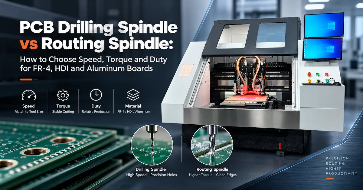
When comparing a new machine or replacement spindle, request the details that let your team connect a specification to a process. Ask whether the spindle is intended primarily for drilling, routing, or both. Ask for the continuous-duty speed range, rated power, torque information if available, cooling method, air or water quality requirements, bearing type at a useful level of detail, and the service procedure for the nose, collet, and taper.
Ask how runout is measured and at what tool length. Ask for the acceptance method for vibration and temperature, including the ambient condition, run time, and load. If the machine includes multiple heads, ask whether all heads are tested under the same conditions. CHIKIN's public product pages describe several machine configurations, including high-speed drilling platforms and drilling-and-routing machines; final spindle parameters and acceptance values still need to be confirmed for the quoted model.
Also ask about the practical support package. Is a replacement spindle stocked? Are bearing service and balancing performed by the maker or a qualified partner? What photographs, logs, or sample panels should be sent when a problem is reported? Does the machine controller preserve spindle alarms and operating hours? A lower purchase price can become expensive if a bearing event stops production for weeks because the diagnostic and spare-parts path was not defined.
12. Choosing Between Repair and Replacement
Repair is attractive when the spindle body, shaft, encoder, cooling circuit, and taper are still within specification and the service provider can document the work. Replacement is often safer when the spindle has had a severe crash, the shaft or taper is damaged, the bearing history is unknown, or the repair lead time competes with a critical production order. The decision should include downtime, validation time, requalification samples, and the risk of repeating the failure.
Do not compare only the price of a bearing kit with the price of a complete spindle. A bearing change can require precision cleaning, preload setting, balancing, runout verification, encoder checks, and a controlled break-in. A complete replacement may arrive with a documented acceptance test, but it can still need alignment, tool-length calibration, and a process coupon. Ask for those deliverables in the quote.
For equipment used across several board families, keep one qualified reference program and coupon. It should include a small-hole pattern, a representative outline, and the most sensitive edge or slot in your normal work. That coupon gives the repaired or replacement spindle a practical pass/fail test instead of relying on a no-load spin alone.
13. How the Machine Design Supports Bearing Life
Bearing life is influenced by the whole machine. A rigid base reduces unwanted structural response. Accurate linear motion reduces the side load created by a poor approach. Tool-length and break detection can stop a damaged tool before it continues to stress the spindle. CCD alignment can reduce the need for repeated corrective passes when a panel is not located correctly. Automatic tool change can improve consistency when the collet, taper, and tool management are maintained properly.
These features should be evaluated as a system. A high-speed spindle installed on a flexible fixture may still produce chatter. A strong routing spindle with a dirty collet may still produce runout. A dust extraction system that leaves debris near the nose can shorten service life even when the spindle motor is correctly sized. This is why the purchase specification should include tooling, clamping, extraction, cooling, software alarms, and acceptance tests alongside RPM and power.
14. Buyer Checklist for a Bearing-Ready PCB Spindle
Before approving a machine or replacement spindle, confirm the following in writing:
- The quoted model, spindle type, rated power, usable speed range, and continuous-duty condition.
- The intended mix of micro-drilling, contour routing, slots, depaneling, and aluminum or special-material work.
- Tool diameter range, collet standard, permissible tool stick-out, and tool balancing requirements.
- Cooling method, flow or pressure requirements, filtration, alarms, and the expected temperature trend.
- Runout measurement point, gauge method, acceptance limit, and the tool or test bar used for the test.
- Vibration or noise acceptance method, including speed, load, sensor position, and recording format.
- Tool-length, tool-diameter, broken-tool, and spindle-temperature alarms included in the controller.
- Spare spindle or bearing lead time, service route, documentation, warranty scope, and training.
- Sample processing using the customer's board, Gerber or ODB++ data, tooling, and target quality criteria.
- Requalification steps after installation, repair, or bearing replacement.
This list turns a general request for a "high precision spindle" into a measurable production requirement. It also gives the sales engineer enough information to recommend a drilling head, routing head, or a combined configuration without guessing from a single board photo.
15. Questions Operators Frequently Ask
Can a noisy spindle finish the current batch?
Sometimes, but a noise change is not a safe production limit. Stop and inspect if the sound is accompanied by heat, vibration, alarms, rising runout, or tool breakage. If the sound is stable and the maker's procedure permits continued operation, run a controlled reference check and set a short review interval.
Does a high temperature always mean bearing damage?
No. Cooling flow, ambient temperature, overload, lubricant, drive settings, and sealing can all change heat. A rising trend under the same recipe is more useful than the absolute temperature felt by hand.
Can I fix runout by changing the collet?
Often, a damaged or dirty collet is the cause. Change one controlled variable, clean the taper correctly, and measure again. If runout remains at the spindle nose with a verified holder, escalate the spindle inspection.
How often should PCB spindle bearings be replaced?
There is no responsible universal interval. Duty, speed, tool load, cooling, contamination, acceleration cycles, and crash history all matter. Use the maker's service guidance and your own trend data, then validate the replacement with a reference coupon.
Is a drilling spindle suitable for routing?
Not automatically. A drilling spindle may have excellent high-speed behavior but insufficient torque, stiffness, or continuous-duty margin for side cutting. Confirm the tool diameter, radial engagement, material, and duty cycle with the supplier.
Conclusion: Treat Small Changes as Process Data
Bearing wear is easier to manage when it is treated as a trend rather than a surprise. Listen at a defined speed, measure temperature at a defined point, capture vibration with a repeatable setup, and check runout with a clean taper and a verified holder. Then compare those results with the board quality that matters to the customer: hole size, registration, wall condition, edge finish, burr level, and tool life.
CHIKIN's public product information shows a range of PCB drilling, routing, CCD alignment, and multi-spindle machine directions. The right spindle configuration depends on the quoted model, board stack, tool mix, output target, and acceptance plan. Provide those details before asking for a price so the supplier can recommend a configuration that is serviceable as well as fast.
Request a PCB Spindle Bearing Health Check and Configuration Review
If a spindle has already shown a new sound, rising temperature, vibration, or runout, send the machine model, spindle hours, tool and holder details, trend readings, alarm history, and a short description of the affected board operation. A clear record allows an engineer to distinguish a likely bearing issue from tooling or process setup and to propose the next test.
Send Spindle Symptoms and Board Requirements for a Custom Quote
Technical note: machine parameters, bearing limits, service intervals, and warranty terms vary by model and configuration. Confirm final values in the official quotation, manual, and acceptance document before production release.