



An edge starts looking rough halfway through a batch. The operator installs another cutter, and the next few panels improve, but the problem returns. Before changing the spindle or reducing feed across the entire program, inspect what is happening around the cut. A partly blocked extraction shoe, a damaged hose, or a loaded filter can leave particles in a slot long enough to be cut again. That does not prove extraction caused the defect. It does make extraction a process variable worth checking rather than a housekeeping task left until the shift ends. For a buyer comparing pcb drilling machine dust extraction, the useful question is not simply whether a collector is supplied. It is whether debris is captured at each working head, with the actual board, tool path, hose layout, and filter condition used in production.

Quick Answer: What Does Dust Extraction Change?
Remove debris where the tool produces it, and there is less material available for recutting or deposition on the fixture. That is the practical benefit. It can help preserve a validated routing process, but it does not make the machine's axes more accurate. Nor does the extraction reading prove that a vacuum table is holding the panel securely. Check collection and retention separately. When ordering equipment, ask to see the relevant readings during a representative program, with the planned heads operating together. A motor rating and a photograph of a clean cabinet cannot answer whether that working condition will last through the batch.
Why Routing and Drilling Need Different Capture Checks
Follow the material, rather than the cabinet's appearance. After cutting FR-4, look for laminate particles and glass fragments; where copper is removed, include metal debris in the inspection. A drill carries material up its flutes. A router throws it into a changing space beside the cutter, which is why a setup that works on a row of holes deserves another check on a long contour. Think of a slot beside a fixture wall: the wall may obstruct the collection path even though the nozzle remains close to the tool. Now move the head to the opposite corner. Does the hose bend tightly there? Does the shoe still clear the fixture? Both positions belong in the demonstration. A pressure foot can define the region around a drill, but buyers still need evidence that particles leave that region. Check below the board too. Material can collect against the support layer while the surface above looks acceptable. For pcb router dust collection, ask the supplier to show the complete programmed route and the residue left in named inspection areas. A straight test cut near the outlet tells you little about those harder positions.
How Debris Can Disturb Accuracy Without Changing Axis Calibration
Consider a panel reloaded onto a fixture with a chip on one support point. The controller has not lost its coordinate, yet the board may sit differently. A local lift changes where the programmed depth meets the surface; with a thin panel, cutting force can also produce movement around that support. This is a seating problem, not evidence that dust changed the axis calibration. Recutting is a different mechanism. Material that remains alongside a small router returns to the cutting edge and makes the load less consistent. If the tool already has long stick-out or limited stiffness, that extra disturbance deserves investigation. Tool seating provides a third route: residue on a gripping or mating surface can interfere with the holder or collet, so scheduled cleaning and runout checks still matter. Look at optical surfaces as well. A dirty fiducial or measurement window can complicate recognition without any movement-system fault. These examples explain how contamination might affect a result; they are not a guarantee that each dusty board will fail tolerance. Before blaming extraction, check the datum, fixture, cutter, spindle condition, and recipe. Better collection will not repair backlash or correct an inaccurate fixture reference.
What Good Extraction Can and Cannot Do for Tool Life
The useful tool-life question is, 'How much conforming routed length did this cutter produce?' A cutter can remain unbroken while its edge quality has already fallen below the customer's requirement. On glass-reinforced laminate, normal cutting wear continues even with good extraction. Collection can remove loosened abrasive material before another encounter with the edge, but it cannot make the laminate non-abrasive. A congested slot adds another concern: particles have less space to escape, and rubbing or recutting may add heat and disturb the finish. How much that matters depends on the cutter, depth, feed, RPM, material, and existing wear. Avoid buying on a promise of twice the tool life unless a comparable test supports it. Instead, fix the tool supplier, diameter, stick-out, board construction, and cutting recipe in the trial. Record routed length and the reason for replacement. Was it roughness, burrs, a dimensional limit, the approved hit count, or breakage? An early replacement with no reason recorded does not support a savings claim. Finally, keep cooling in the comparison: air passing through an extraction shoe does not replace the spindle's thermal-control system, and increasing suction cannot correct an unsuitable recipe.
Extraction Vacuum and Workholding Vacuum Are Separate Jobs
When a quotation says 'pcb cnc vacuum system', ask the supplier to identify its job on a diagram. Is it drawing particles through a shoe, evacuating a table to retain the board, or doing both through an engineered arrangement? These jobs need different evidence. Schmalz's explanation of vacuum clamping relates holding force to the pressure difference and the effective area; friction also matters when resisting lateral cutting force. A pressure reading at the collector cannot tell you that a panel has adequate retention. Look at the last contour in the program, not just the loading stage. Once a cut breaks through, it may open a leak or leave a small part with less usable holding area. The fixture might require tabs or a dedicated carrier, depending on the job. At the same time, the collection shoe must clear that fixture without dragging its skirt across delicate material. If a supplier proposes a shared vacuum source, have it explain how retention survives changes in extraction demand. A compatible hose connector is not a design justification. Put the approved workholding condition and extraction condition into separate acceptance records so a later fault can be traced to the correct system.
| Function | What it controls | Useful acceptance evidence | What is not enough |
|---|---|---|---|
| Tool-zone extraction | Debris leaving the cutting region | Capture observations and measured branch performance | Collector motor power alone |
| Vacuum workholding | Panel retention on the fixture | Holding vacuum and board stability during breakthrough | Suction measured at the dust collector |
| Spindle cooling | Motor and spindle thermal conditions | OEM-specified coolant or cooling-system checks | Air passing through the dust shoe |
| Enclosure extraction | Airborne residue within the chamber | Verified airflow pattern and clearance procedure | A closed cabinet door |
| Final filtration | Particle separation before discharge | Appropriate filter specification and system checks | A filter label without installation evidence |
Airflow, Pressure, and Hood Position: Specify the Installed System
Suppose a collector's brochure gives a maximum airflow on one line and a maximum vacuum on another. Do not combine them into a working specification: they may represent opposite ends of its performance curve. What you need is flow at the pressure required by the installed circuit. Follow that circuit from the tool: shoe, moving hose, bends, branch connections, separator where fitted, filter, and air mover. Each part contributes resistance. The machine supplier should state its connection requirements; the extraction designer should show how they are met. For several working heads, identify the simultaneous operating combination before comparing collector capacity. Then check individual branches, since a strong short branch does not establish performance at a longer one. Hose changes deserve attention too. Reducing diameter can increase pressure loss, while increasing it at unchanged flow can lower transport velocity. The convenient hose in stores may therefore be the wrong replacement. At the tool, too much shoe clearance offers particles an escape path; too little can interfere with fixtures. Have the demonstration cover both travel extremes, where the moving hose takes a different shape. Put the installed layout, test point, active heads, filter condition, and minimum accepted reading on the commissioning sheet. Without those details, the same airflow number can describe very different machining conditions.
Filters Load Gradually; Capture Can Decline Before Anyone Notices
A collector still running is not necessarily a collector still delivering its commissioned airflow. As particles load the filter, resistance changes. Donaldson discusses this relationship in its technical explanation of filter cleaning. For the purchase specification, ask how the required machine flow is maintained up to the approved filter-service limit, not merely what happens with new media. Keep two observations in the service record: filter differential pressure and the agreed indication at the branch. If the first appears normal but dust remains beside one spindle, a local obstruction or damaged connection still needs attention. A surprisingly low filter reading is not automatically good news either; check operating conditions and filtration integrity against the approved baseline. Before choosing a pcb dust extractor, get the material mix and discharge arrangement reviewed. A filter labelled HEPA may suit a design, but that label does not establish that the complete installation contains particles or that recirculated air is acceptable. Fine-particle suitability, seals, accessible servicing, and replacement-media supply all belong in the comparison. The site's competent assessor should determine exposure controls and any static or combustible-dust precautions from the materials and process. In particular, do not add aluminum or other metal residues to a laminate collection stream without a compatibility review. Ask how waste is segregated and removed, and include that task in operator training.
A Simple Airflow Calculation That Does Not Replace a Capture Test
Volumetric flow follows the relationship Q = v x A, where Q is flow, v is mean air velocity, and A is the duct's internal cross-sectional area. Consider an illustrative 40 mm internal-diameter connection. Its area is approximately 0.00126 square metres. If a properly taken measurement gives a mean velocity of 15 metres per second, the calculated flow is about 0.0189 cubic metres per second, or 68 cubic metres per hour. Neither 40 mm nor 15 metres per second is a recommended PCB extraction target here. The example only shows how diameter, velocity, and reported flow relate. A reading at the centre of a hose is not necessarily its mean velocity, and turbulence near a bend can make a convenient measurement unreliable. Use the equipment supplier's approved test arrangement. If four branches each need an agreed flow, the collector must accommodate their simultaneous demand at the installed resistance, but multiplying one branch value by four does not prove balance. One short branch may draw disproportionately while a longer one receives too little. The test record should therefore state the branch identity, active-head combination, hose arrangement, filter condition, instrument, and measurement location. Repeating those conditions later turns a number into a useful maintenance benchmark instead of a misleading catalogue comparison.
Local Collector or Central Plant System? Check the Trade-Off
A local collector can make responsibility clear: one machine, a short connection, and service readings that relate to that machine. It still occupies floor space and requires waste handling, noise assessment, and scheduled filter service. A central system can consolidate servicing and keep collectors outside the production area, but its longer ducts and changing demand need careful coordination. Starting another machine or changing a gate must not leave a PCB head below its commissioned capture condition. Before connecting to an existing plant system, obtain its available capacity and confirm material compatibility rather than relying on spare-looking ductwork. Ask who owns the alarm response when the machine belongs to production but the collector belongs to facilities. That small organisational detail matters during a night shift: the operator needs an approved response and a named contact, not a debate over whether a dust problem is a machine fault or a building-services fault.
Diagnose the Symptom Before Replacing the Spindle
A rough edge is not a unique signature of weak extraction. A blunt cutter, unsuitable chip load, excessive stick-out, poor support, or a loose fixture can produce a similar result. Use debris patterns and process records to narrow the investigation. If a single head is affected while adjacent heads remain clean, inspect that branch before adjusting the common collector. If all heads deteriorate later in the shift, look at filter loading, collection-bin condition, and shared duct restrictions. When an issue appears only at one panel corner, check hose motion and shoe clearance at that position. After correcting a fault, verify the result with the same material and an approved recipe. Avoid changing the cutter, feed, fixture, and extraction setting simultaneously, because the improvement then has no clear cause. Effective drilling debris removal also needs checks near entry and exit surfaces, not just an empty cabinet at the end of the program. Debris left underneath a stack may escape a quick visual check from above. Make inspections repeatable by naming the locations to inspect, the approved cleaning method, and the quality measure used to accept the next panel.
| Observed symptom | Extraction-related possibility | Other cause to exclude | First verification |
|---|---|---|---|
| Dust remains beside one spindle | Blocked shoe or unbalanced branch | Different cutting load at that head | Compare branch readings under matched conditions |
| Edge finish worsens during a batch | Increasing restriction or recutting | Cutter wear or recipe drift | Review airflow, filter trend, and tool record |
| Board shifts near the last contour | Contamination or capture interference | Reduced holding area or fixture leakage | Inspect seating and workholding vacuum |
| Hole exits contain residual debris | Incomplete local evacuation | Backing material or drill strategy | Inspect underside and support arrangement |
| Tool seating becomes inconsistent | Residue on tool interfaces | Damaged collet or holder | OEM-approved cleaning and runout check |
| Filter pressure rises unusually fast | Heavy loading or ineffective cleaning | Incorrect filter or process change | Check media, cleaning mechanism, and material mix |
A Maintenance Plan That Preserves the Validated Process
Dust-related maintenance becomes easier when the plan follows the particle path: cutting zone, hose, separator, filter, waste container, and discharge. Before a shift, check the extraction indication, hose condition, shoe position, and collection level according to the equipment manual. During approved stops, inspect fixture contact areas, vacuum seals, and accessible measurement surfaces. Follow the machine maker's procedure for cleaning collets and tool interfaces; do not push debris into spindle seals or air-bearing supplies. Guideways, ballscrews, wipers, and lubrication points need their own inspection routine because contamination that reaches them can increase maintenance demand. Avoid treating compressed-air blowdown as the default cleaning method: it can redistribute settled dust into breathing zones and protected machine areas. Use approved contained cleaning methods and the site's exposure-control procedure. A starting schedule should distinguish operator checks, planned service, and specialist inspection, then be adjusted from actual loading and manufacturer guidance. Frequent filter changes are not automatically good maintenance if the real fault is a poor shoe seal or excessive waste loading. Equally, long filter life is not evidence of good capture if little material is reaching the collector. Log airflow indications, filter pressure, waste level, hose repairs, cleaning time, and relevant quality issues together so the team can see whether maintenance restores the expected condition.
How to Accept a New Machine Without an Artificially Easy Demonstration
Factory acceptance should use representative work: the longest contour, a narrow slot, a dense drilling program, or a challenging support arrangement. For populated boards, include component clearances and any cleanliness requirement specified by the customer. Agree the fixture, cutter, material, program, and inspection method beforehand. Record extraction readings with the intended simultaneous heads operating, and inspect residue at predetermined locations. Compare the first and later accepted panels, rather than relying on a single demonstration coupon. Assess tool wear only over a meaningful, agreed cutting length; a short video cannot establish long-term cutter life. Ask how airflow is maintained throughout the approved filter-service range. Any simulation of resistance or alarm testing must use the supplier's safe method, not deliberate uncontrolled blockage or cutting with extraction disabled. Verify the agreed response to insufficient flow: warning, controlled pause, or another OEM-defined action. The HSE's LEV commissioning guidance provides a useful general framework of benchmark flow and pressure targets plus demonstrated control under stated conditions. The particular safety and exposure checks for your plant should be determined by competent local personnel. Recheck the system after installation, because site hoses, building ventilation, and shared-collector connections may differ from the supplier's factory. Keep that site record as the baseline for later fault finding and service decisions.
What PCB Buyers Should Ask CHIKIN to Confirm
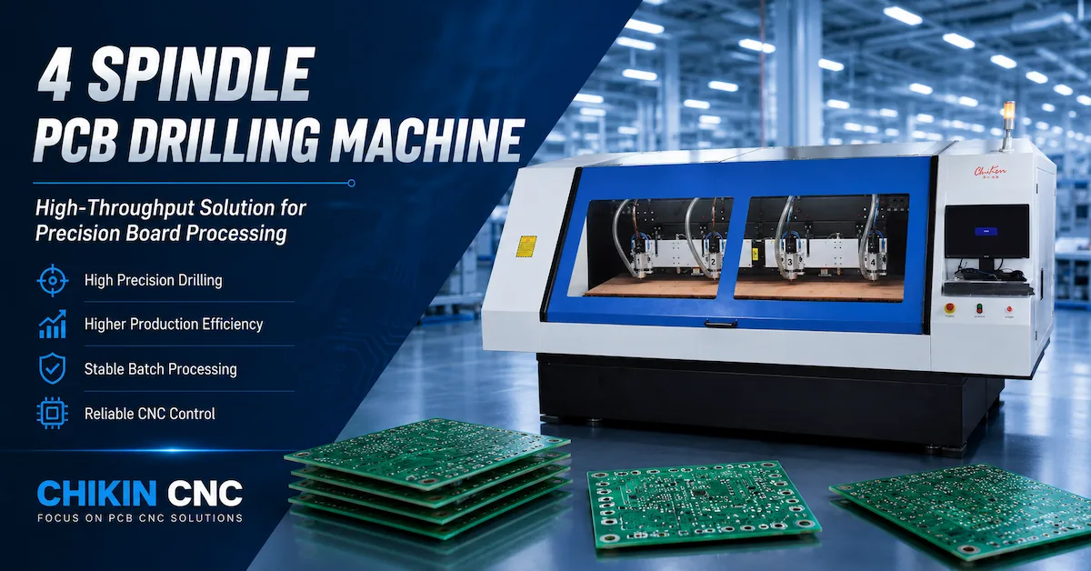
CHIKIN's CK-04R product page lists four 60,000 RPM, 1.8 kW water-cooled spindles, automatic tool change, and tool-detection functions. Its 1 Drill 1 Route with CCD page describes dedicated drilling and routing heads with vision alignment. Those descriptions provide machine context, but they do not publish a complete installed extraction design. Request the exact collector scope, connection sizes, branch requirements, filtration, utilities, and control interface in the quotation. Clarify whether extraction is included, optional, or supplied by the customer's plant. Send board material and thickness, panel dimensions, hole count, routed length, smallest tool, active-head count, shift pattern, and the planned collector location. Add fixture geometry, populated-board clearances, and existing vacuum-workholding details where relevant. Define who supplies hoses, grounding provisions where required, waste handling, commissioning, and training. For purchasing comparisons, examine total installed cost rather than collector price alone: replacement media, electricity, service time, extraction-related stoppages, and rejected panels matter. Useful measures include cleaning minutes per shift, conforming routed length per cutter, and accepted panels per operating hour. Do not book savings from dust extraction until the baseline and the demonstrated improvement have been measured on comparable production.
Request a PCB Dust Extraction Configuration Review
Buyer Questions: Airflow, Accuracy, and Collection Options
Does stronger extraction automatically make PCB routing more accurate? No. Adequate capture can remove contamination-related disturbances, but machine calibration, tool runout, fixtures, board stability, and cutting parameters still determine the result. Uncontrolled suction or a poorly adjusted shoe can introduce interference. Specify the capture condition needed for the process rather than maximizing suction without a defined test.
Can one collector serve several spindles? Yes, when designed for the simultaneous demand and properly balanced. A good total airflow reading can coexist with one underperforming branch. Ask for verification at each working connection and confirm how the system behaves when heads, gates, or programs change.
What airflow should a PCB dust extractor provide? There is no reliable universal value for every machine and board. Request flow and pressure requirements at stated connection points, with the intended hoses, shoes, head count, and filter condition. The supplier should explain the measurement method and the threshold used for service or alarms.
Will a dust extractor replace panel cleaning? Not automatically. Capture and final product cleanliness are separate acceptance questions. Inspect representative boards against the customer's cleanliness requirement; retain a validated downstream cleaning step wherever source capture alone does not meet it.
What belongs in the purchase contract? Include extraction scope, installed performance conditions, filtration and discharge arrangements, workholding separation, maintenance instructions, spare-filter availability, alarm behavior, and acceptance responsibilities. A statement that a machine has a vacuum connection is not an extraction-performance guarantee.
Conclusion: Treat Extraction as Part of the Machining Process
PCB drilling machine dust extraction earns its place in the technical specification because debris can interfere with a cut, a fixture, a tool interface, and routine maintenance. It is not a shortcut around poor tooling or a substitute for calibration. The better buying decision is to verify capture where particles are produced, check performance as filters load, protect independent workholding, and record the accepted operating condition. For a routing line, that creates a defensible maintenance baseline rather than a collector selected by motor size. Send CHIKIN your real board, route, tool list, head configuration, and installation layout, then request a configuration and acceptance proposal that names what is included and what still needs site validation.