



When a PCB factory starts comparing spindle specifications, the first question is often simple: which spindle has the higher RPM? That question is understandable, but it rarely leads to the right machine. A spindle is not selected in isolation. It is selected for a tool diameter, a material stack, a cutting direction, a hole or outline requirement, a production schedule, and a maintenance plan. A very fast spindle can be the wrong choice for a heavy routing pass. A powerful routing spindle can be a poor choice for a micro-drill that needs clean entry and exit at high speed.
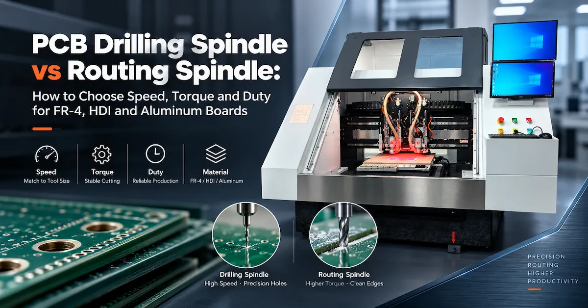
This is the practical meaning of drilling spindle vs routing spindle. The difference is not only the label on the motor. It is the way the spindle converts electrical power into cutting behavior. A drilling spindle is normally optimized for small rotating tools, low radial load, short peck cycles, and repeatable hole position. A routing spindle is normally optimized for end mills, slots, board outlines, heavier side load, and a more continuous engagement with the workpiece.
For PCB manufacturers, that distinction affects five outcomes that are easy to measure on the shop floor: hole wall quality, edge finish, tool breakage, cycle time, and cost per good panel. This guide explains the differences in plain engineering terms and then turns them into a purchase checklist. The goal is not to declare one spindle universally better. The goal is to help a buyer specify the spindle that matches the work.
The short answer: drilling is about clean axial entry; routing is about controlled side load
A drilling spindle pushes a small drill into the board along the Z axis. The tool must stay straight while it cuts copper, resin, and glass reinforcement. The process rewards high speed, low runout, accurate Z control, good chip evacuation, and a spindle bearing system that can survive repeated starts and stops. A routing spindle drives an end mill through an outline, slot, pocket, or edge. The tool is exposed to radial cutting forces. The process rewards torque, stiffness, stable speed under load, cooling capacity, and a motor that can run for long periods without thermal drift.
There is overlap. Both spindles need low vibration, accurate bearings, reliable collets, balanced tooling, and a machine frame that does not move when the tool enters the material. A modern PCB CNC machine may use separate drilling and routing spindles, or it may use a configurable spindle and tool library. The correct solution depends on the mix of holes and contours in the production queue.
| Decision factor | PCB drilling spindle | PCB routing spindle | Why it matters |
|---|---|---|---|
| Primary motion | Axial plunge and retract | Continuous XY engagement with Z depth control | Drilling stresses the tool along its axis; routing adds side load. |
| Typical tool | Micro-drill, often carbide | Carbide router, end mill, slot cutter or V-bit | Tool geometry sets the required speed and torque. |
| Preferred speed | Very high RPM for small diameters | Lower or medium RPM with useful torque | Surface speed rises quickly as tool diameter increases. |
| Torque demand | Usually modest, but sensitive to runout | Higher, especially in slots and thick stacks | Torque prevents speed collapse and edge damage. |
| Duty pattern | Many short cycles and frequent Z moves | Longer cuts and sustained load | Cooling and bearings must match the heat profile. |
| Typical risk | Broken drill, oversized hole, smear, poor registration | Chatter, burrs, delamination, tool deflection | Different failure modes require different controls. |
| Best fit | Vias, through holes, tooling holes, small apertures | Board outlines, slots, pockets, depaneling and edge work | The operation should determine the spindle. |
1. Speed: why RPM is useful, but never enough on its own
RPM matters because it controls cutting speed at the tool edge. For a rotating tool, the approximate surface speed is:
Cutting speed (m/min) = pi x tool diameter (mm) x RPM / 1,000
As the tool becomes smaller, the spindle must turn faster to maintain a useful edge speed. That is why a micro-drill used for a small PCB hole may need a much higher RPM than a 3 mm routing cutter. If the spindle speed is too low for a small drill, the tool can rub instead of cut. Heat rises, the hole wall becomes less clean, and the drill may break before it reaches the programmed depth.
A drilling spindle is therefore commonly designed around high RPM. On its CK-04D product page, CHIKIN lists four high-speed air-bearing spindles in the 160,000 to 200,000 RPM range, with a stated drilling tool range of 0.15 to 6.35 mm. That is a model-specific specification, not a universal rule for every PCB drilling spindle. It shows the kind of speed envelope used when a production line must process many small holes with controlled runout.
A routing spindle uses a different speed balance. The cutter is larger, and the work is often a side-cut rather than a simple plunge. Excessive RPM can polish or burn the resin, shorten cutter life, and make chip evacuation harder. More importantly, RPM without torque does not guarantee a stable cut. CHIKIN lists 60,000 RPM and 1.8 kW per spindle for its CK-04R drilling and routing machine, with a routing tool diameter range of 0.5 to 3.175 mm. That combination is a useful example of how a routing spindle can still be fast while preserving enough power for contour work.
When buyers search for pcb drilling spindle options, they should request the recommended RPM range for each drill diameter, not only the maximum motor speed. When they compare pcb milling spindle speed, they should request the speed, feed, axial depth, radial engagement, and material combination used to obtain the published result. A maximum number is a starting point; a validated cutting window is what production needs.
2. Torque: the difference that appears when the tool meets resistance
Torque is the turning force available at the spindle shaft. In simple terms, torque helps a motor keep turning when the tool encounters resistance. Power and speed are related by the familiar relationship:
Power (kW) is proportional to torque (N.m) x RPM
That relationship explains why two spindles with similar power can feel very different in a cut. One may deliver its power at a very high speed with relatively little torque. Another may be tuned to hold more torque at the speed used for an end mill. Neither is automatically better. Each is better suited to a different operation.
During drilling, the cutting edge removes a small circular area while the tool moves mostly along Z. The radial load is limited if the tool is sharp, the hole is correctly programmed, and the board stack is supported. The bigger concern is runout, tool balance, drill deflection, and chip evacuation. A drilling spindle does not need to behave like a heavy milling motor, but it must maintain clean rotation at very high speed.
During routing, the end mill cuts on its side. The board outline can create a long continuous cut, and a slot can keep the cutter engaged on both sides. A warped aluminum substrate or a thick multilayer stack can increase the load again. If the pcb router spindle cannot hold speed, the result may be chatter, a rough edge, delamination, or a sudden rise in current. More torque does not remove the need for good feeds and speeds, but it gives the process a larger stability margin.
Buyers should ask for a torque curve or at least the rated power and usable speed range. Ask whether the rating is continuous or peak. Ask what happens when the tool is engaged in a 1 mm slot through a particular FR-4 thickness. A spindle with a high headline RPM but a narrow useful torque band may be a poor match for heavy routing. Conversely, a large torque-oriented motor may add mass and cost that bring no benefit to a line making thousands of small holes.
3. Tooling: drill geometry and router geometry create different spindle demands
Tooling is where a spindle comparison becomes practical. The spindle, collet, holder, tool, feed, and material form one cutting system. If one component is changed, the recommended operating window changes as well.
Drilling tools
PCB drills are usually small-diameter carbide tools with a point geometry intended to penetrate copper and laminate cleanly. They are not designed to tolerate the same side load as a router. Runout that looks insignificant on a large cutter can become a large percentage of a micro-drill diameter. That is why a drilling spindle needs a precise taper, clean collet, accurate tool length measurement, and a stable Z axis.
Drill life is also affected by the stack height. More layers mean more material to evacuate and more heat in the tool. A peck strategy, pressure foot, vacuum path, and support board can be as important as the spindle motor. A buyer who only compares RPM may miss the features that actually protect the drill.
Routing tools
Routing tools include straight cutters, compression-style cutters, slot mills, and small end mills. Their diameter is usually larger than a micro-drill, and their cutting edges experience side force. Tool stick-out should be kept as short as the fixture and clearance allow. A long, slender cutter may deflect even when the spindle itself is rigid.
For routing, the relationship between chip load and feed is important:
Feed rate = number of flutes x chip load x RPM
If the feed is too slow at a high RPM, the tool can rub and generate heat. If the feed is too fast for the tool diameter and board construction, the cut can pull copper or damage the edge. A good pcb spindle motor is therefore only one part of the routing result. The machine needs the right tool library, collet runout, tool length control, and process recipe.
Automatic tool management
Automatic tool change, tool length detection, tool diameter detection, and broken tool detection can be more valuable than a small increase in rated speed. CHIKIN lists these functions on several of its drilling and routing machines. They help reduce manual setup errors and make it easier to manage a mixed program containing drill sizes, routing cutters, and finishing tools.
However, "automatic" should be clarified during procurement. Ask how many positions are available, how the machine identifies a tool, whether broken tool detection is optical or load-based, how the system reacts after an alarm, and how worn tools are removed from the production record. Those details determine whether the feature saves time in daily production or simply appears in a brochure.
4. Duty cycle: short high-speed bursts versus sustained cutting
Duty is the part of a spindle specification that is often missing from online comparisons. Two machines may both be described as suitable for continuous production, yet their thermal behavior can be very different.
PCB drilling frequently consists of many short cycles: rapid positioning, plunge, retract, move to the next coordinate, and repeat. The average cutting load may be modest, but the spindle experiences repeated acceleration, braking, and tool changes. The bearing system must remain stable at high speed, and the cooling circuit must remove heat even when the cutting load changes quickly.
PCB routing often includes longer periods of engagement. A board outline may run for several minutes, and a slot or pocket can keep the tool loaded continuously. The motor, bearings, collet, machine frame, fixture, and dust extraction system all see a sustained load. Thermal growth can change the relationship between the tool and the board. The longer the cut, the more important it becomes to control coolant temperature, cabinet airflow, bearing preload, and chip evacuation.
When a supplier says a spindle is suitable for 24/7 use, ask what "24/7" means. Does it mean the machine can remain powered on? Does it mean a shift pattern with tool changes and loading pauses? Or does it mean a verified continuous cutting test at a stated tool, feed, depth, and material? A responsible RFQ should ask for the test condition and the maintenance interval.
5. Cooling and bearings: the quiet factors behind repeatability
High-speed drilling spindles commonly use air bearings or precision angular-contact bearing systems, depending on the design. Air-bearing systems can offer very low friction and good high-speed behavior, but they require clean, dry, stable air and correct pressure. A contamination problem in the air supply can become a spindle problem. If the machine is installed in a humid or dusty environment, the air preparation system must be included in the purchase plan.
Routing spindles often use water cooling or another thermal management method because the motor can be exposed to longer cutting loads. CHIKIN lists water-cooled 60,000 RPM spindles on its CK-04R product page and water-cooled spindle options on its 1 Drill 1 Route with CCD page. Water cooling is not a substitute for a correct process recipe, but it helps the motor hold a stable operating temperature during repeated routing work.
For both types, ask about the cooling medium, flow rate, chiller capacity, alarm logic, filter replacement, and the effect of a cooling fault. Ask whether the spindle is rated for the ambient temperature in your plant. Thermal drift can show up as changing hole position, outline size, or board edge quality before an operator sees a clear alarm.
6. Machine stiffness and vibration: the spindle cannot compensate for a flexible frame
It is tempting to treat the spindle as the complete cutting solution. In reality, the spindle is only as stable as the machine that holds it. A flexible gantry, loose fixture, uneven sacrificial board, or contaminated collet can erase the advantage of a premium motor.
A drilling process is sensitive to axial alignment and vibration. A small oscillation can enlarge a hole or damage the entry surface. A routing process is sensitive to radial stiffness. A small amount of deflection can change the outline dimension, create a tapered edge, or pull the cutter out of the programmed path.
CHIKIN describes granite bases, high-accuracy linear guides, and ballscrews on several PCB machines. These features are useful because mass and damping help isolate the cut from structural vibration. They should still be verified in a sample test. The test should measure the actual hole position, outline dimension, edge finish, and repeatability on the buyer's own board stack, rather than relying on a general claim about the frame material.
7. Which spindle fits common PCB materials?
FR-4 and multilayer boards: A high-speed drilling spindle is normally used for plated and non-plated holes, while a routing spindle handles the outline, slots, and local cutouts. Glass reinforcement increases tool wear and can influence edge quality. Tool life data should be collected on the customer's actual layer count and copper condition.
HDI and fine-pitch boards: Small holes and tight registration place extra emphasis on spindle runout, Z control, tool inspection, and fiducial alignment. A dedicated drilling spindle is generally the more natural starting point. A CCD-equipped hybrid machine can be useful when drilling and routing must happen in the same setup, provided the alignment workflow is validated.
Rigid-flex boards: The flexible section needs careful support. Drilling and routing parameters should account for the transition between rigid and flexible areas. Pressure foot design, vacuum, fixture support, and tool entry are often more important than a headline RPM number.
Aluminum substrates: Aluminum changes the thermal and cutting load. A routing spindle with controlled torque and cooling may be more suitable for mechanical contours. For larger or complex metal-base profiles, CHIKIN also presents a fiber laser cutting direction. Buyers should compare mechanical routing and laser processing by edge quality, heat-affected zone, secondary finishing, and total cost rather than choosing only by nominal speed.
Copper and mixed-material panels: Copper can smear or generate heat when the tool and feed are not matched. The correct tool coating, chip evacuation, support, and cutting window should be demonstrated on a sample. A motor that is stable at the chosen speed matters more than the maximum speed printed in a catalog.
8. A practical selection table for production managers
| Your production condition | First spindle direction to evaluate | Questions to put in the RFQ |
|---|---|---|
| Many holes below 0.5 mm, high panel count | Dedicated high-speed drilling spindle | Runout, RPM window by drill size, air quality, Z repeatability, broken drill detection |
| Drilling and board outline in one setup | 1 Drill 1 Route hybrid with CCD | Fiducial method, changeover time, tool range, alignment result, routing torque |
| Long contours, slots or depaneling | Routing spindle with stable torque | Continuous power, torque curve, cooling, edge quality, dust extraction |
| High-mix, low-to-mid volume | Flexible hybrid or two-spindle platform | Tool magazine, recipe management, setup time, operator training |
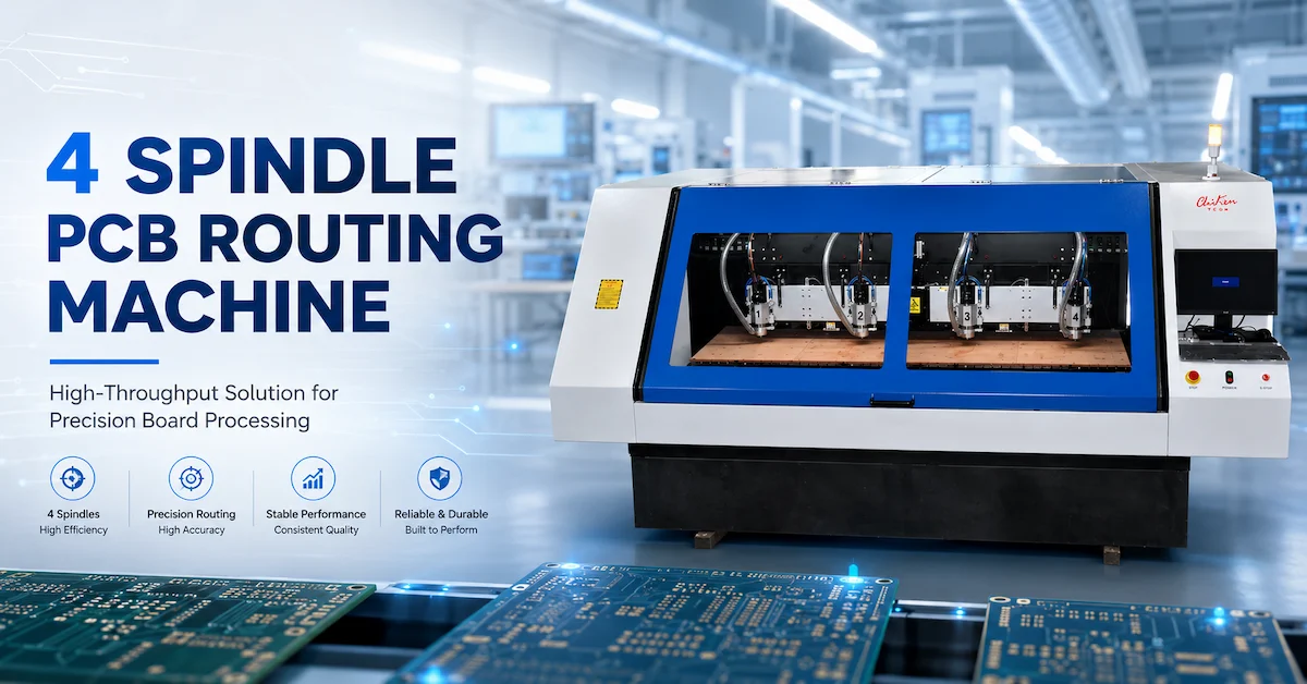
| High-volume identical panels | Multi-spindle drilling or routing line | Parallel processing, loading balance, maintenance intervals, spare spindle plan |
| Aluminum or copper substrate | High-torque routing or laser comparison | Heat control, burrs, HAZ, assist gas, secondary finishing and sample acceptance |
9. Why a two-spindle drilling and routing machine can be a strong middle ground
A factory does not always have to choose between one general-purpose spindle and two completely separate machines. A two-spindle platform can assign drilling to a high-speed head and routing to a more torque-oriented head. That arrangement avoids repeated tool swaps and can reduce the number of times a panel is unclamped.
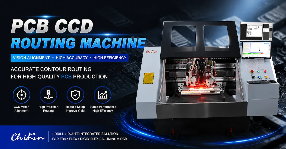
CHIKIN describes its 1 Drill 1 Route with CCD machine as a hybrid solution with a dedicated drilling spindle, a dedicated routing spindle, automatic tool change, tool length and diameter detection, broken tool detection, and real-time fiducial recognition. The page lists a typical drilling diameter range of 0.15 to 6.35 mm and a routing range of 0.5 to 3.175 mm. It also says the platform is intended for NPI-to-mid-volume work on multilayer, rigid-flex, aluminum, and HDI boards. Those are product-page claims that should be checked against the buyer's sample.
The trade-off is that a hybrid machine may not match the absolute throughput of a dedicated four-spindle drilling line for a very large hole program. It may also need a carefully planned fixture because both operations share the same working envelope. The right question is whether the reduction in handling and setup time is worth more to the factory than the maximum drilling capacity of a dedicated line.
10. How to compare quotations without being misled by RPM
When three suppliers quote different spindle packages, place the offers into the same comparison sheet. Start with the process, not the motor. Write down the board material, thickness, stack height, smallest hole, largest router, outline length, number of panels per hour, and required edge quality. Then ask every supplier to quote a test using the same data.
- Check the usable speed range. Record the speed range at the tool diameters you actually use. A maximum RPM without a recommended operating window is incomplete.
- Check power and torque at working speed. Ask whether the rating is continuous, peak, or inverter-limited. Routing performance should be judged under load.
- Check runout at the collet. Ask how it is measured, at what distance from the taper, and with which tool or gauge.
- Check cooling and utilities. Include chiller, air dryer, filters, extraction, electrical load, and alarm interlocks in the total cost.
- Check tooling support. Confirm compatible collets, tool lengths, magazine positions, supplier recommendations, and local availability.
- Check duty and service. Ask for maintenance intervals, bearing replacement procedure, spare spindle lead time, and remote diagnostic support.
- Check the acceptance test. Define hole position, hole size, outline tolerance, edge finish, cycle time, and repeatability before the order is released.
This process also prevents a common mistake: choosing a spindle because it appears fast on paper, then discovering that the machine needs a lower speed, a special fixture, or a slower feed to produce an acceptable edge. The best quotation is the one that explains how the spindle will make good panels at the required cost.
11. Maintenance differences that affect uptime
Drilling spindle maintenance starts with cleanliness. Collets, tapers, drill holders, pressure feet, and the work surface should be kept free of resin dust and chips. A small particle between the tool and taper can create runout. Air-bearing systems need clean, dry air. The machine should record spindle hours and tool changes so a bearing or tool-holder issue can be investigated before it becomes a quality escape.
Routing spindle maintenance adds the burden of chip load and sustained cutting. Extraction must prevent chips from collecting around the collet and cooling passages. The operator should watch for a change in spindle current, sound, edge finish, or vibration. A cutter that is technically still rotating may already be dull enough to damage copper or delaminate the board.
For both spindles, preventive maintenance should include collet inspection, tool-holder cleaning, cooling checks, cable and hose inspection, axis lubrication, calibration, and a repeatability check. The exact interval depends on the machine and production conditions. Ask the supplier for a maintenance schedule that names the consumables and the skills needed to carry it out.
12. The buyer's RFQ checklist
Before requesting a quotation, prepare the following information. A supplier can make a better recommendation when the process is described precisely.
- Board material: FR-4, HDI, rigid-flex, aluminum, copper, FPC, or a mixed stack.
- Board and panel dimensions, thickness range, stack height, and maximum warp.
- Smallest and largest hole, hole quantity, plated or non-plated status, and critical registration points.
- Outline length, slot width, pocket depth, corner radius, and required edge finish.
- Target panels per hour, shift pattern, changeover frequency, and expected production growth.
- Tool diameters, flute count, tool length, preferred suppliers, and acceptable tool cost.
- Required CCD or fiducial alignment, flip-side processing, multi-up panels, and fixture format.
- Available power, compressed air quality, cooling water or chiller, extraction, floor space, and network connection.
- Software files: Gerber, Excellon, ODB++, CAD, or the format used by the existing line.
- Acceptance criteria for accuracy, edge quality, cycle time, noise, dust, training, warranty, and spare parts.
Send a representative board rather than a perfect demonstration panel whenever possible. The right spindle is the one that handles the difficult part of the job: the small hole that breaks drills, the long contour that warms the motor, the aluminum edge that leaves burrs, or the flexible section that moves under pressure.
Conclusion: choose the cutting behavior, not the headline RPM
The difference between a drilling spindle and a routing spindle is a difference in cutting behavior. Drilling rewards high rotational speed, very low runout, accurate axial control, clean air or cooling, and reliable tool monitoring. Routing rewards stable torque, structural stiffness, thermal control, correct chip load, and a tool holder that can resist side force. Both require a rigid machine, a clean fixture, a measured tool library, and an acceptance test based on real boards.
If your factory makes mostly micro-holes, start with a dedicated high-speed PCB drilling spindle. If it makes long outlines, slots, or depaneling cuts, start with a torque-oriented PCB router spindle. If the same panel needs both operations and changeovers are expensive, evaluate a two-spindle drilling and routing platform with CCD alignment. For high-volume lines, compare the cost of multiple spindles against the balance of loading, inspection, maintenance, and downstream capacity.
CHIKIN CNC publishes drilling, routing, hybrid CCD, AOI, laser, and V-CUT solutions for PCB production. Use the product pages as a starting point, then confirm the exact spindle, tool range, speed window, cooling, duty cycle, and acceptance criteria with a sample-processing review.
Request a PCB Spindle Selection Review
Frequently asked questions
Is a higher-RPM spindle always better for PCB drilling?
No. Higher RPM can support small drills, but the correct speed depends on drill diameter, material, feed, stack height, runout, and chip evacuation. A validated speed window is more useful than a maximum RPM number.
Can one spindle perform both drilling and routing?
It can, but the compromise should be tested. A dedicated drilling head and a dedicated routing head can reduce tool changes and preserve the process window when both operations are frequent.
What should I ask about a PCB spindle motor?
Ask for continuous power, torque or torque curve, usable speed range, runout measurement, cooling, bearing type, collet system, tool-change method, duty-cycle test, service interval, and spare-part lead time.
Why can a router spindle make a rough PCB edge even when the RPM is high?
Rough edges can come from insufficient torque, incorrect chip load, tool deflection, worn cutters, poor fixturing, vibration, or inadequate extraction. RPM alone cannot correct those conditions.