



TL;DR — Quick Answer
A PCB depinning machine is designed to remove compatible pins from printed circuit boards or laminated PCB assemblies through a controlled mechanical operation. In multilayer PCB manufacturing, depinning can be used to remove registration or tooling pins after the relevant pinned production stage.
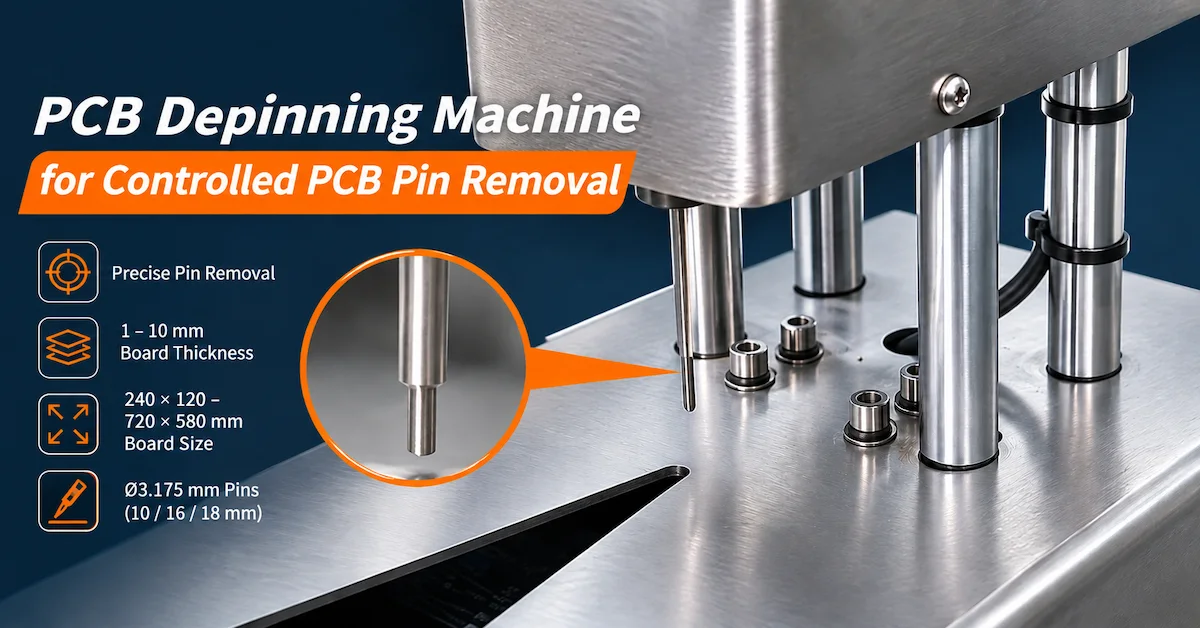
The CHIKIN CNC CK-16 is a compact PCB pin removal machine with a published board-size range of 240 × 120mm to 720 × 580mm, a laminated PCB thickness range of 1–10mm, and tooling pin specifications of Ø3.175 × 10mm, Ø3.175 × 16mm, and Ø3.175 × 18mm.
For PCB manufacturers, the most important selection factors are pin compatibility, board support, removal alignment, laminate integrity, and repeatable operation.
This guide explains the CK-16 specifications, pin removal workflow, quality-control requirements, and purchasing checks to help factories evaluate equipment before investing.
Key Takeaways
-
Application: The CK-16 is intended for controlled PCB pin removal, with published specifications particularly relevant to laminated boards and tooling pins.
-
Board compatibility: The listed PCB size range is 240 × 120mm to 720 × 580mm.
-
Pin specifications: Three listed pin configurations share a nominal diameter of 3.175mm, with lengths of 10mm, 16mm, and 18mm.
-
Quality priority: The pin removal operation should not introduce unacceptable laminate damage, registration-hole deformation, or panel distortion.
-
Procurement requirement: Buyers should verify actual tooling, actuator force, stroke, handling method, safety systems, and sample results before ordering.
1. What Is a PCB Depinning Machine?
A PCB depinning machine is industrial equipment used to remove pins from suitable printed circuit boards, laminated panels, or other approved PCB tooling assemblies.
Pins may be used to locate, secure, or align materials during manufacturing.
After the relevant processing stage, they may need to be removed before the board continues to another operation.
In multilayer PCB production, registration pins can be associated with layer alignment and lamination tooling.
When the process requires their removal, uncontrolled manual extraction may create additional handling risks.
A dedicated depinning station can provide a more defined support and removal arrangement.
Why Is Controlled Pin Removal Important?
PCB laminates may contain glass-reinforced resin systems, copper layers, and multiple bonded layers.
Depending on the application, improper pin removal can cause local damage around tooling holes or introduce unnecessary force into the board.
Potential problems include:
-
Damaged registration holes.
-
Local laminate cracking.
-
Board deformation.
-
Incorrect pin extraction direction.
-
Residual pin fragments.
-
Additional operator handling.
-
Production delays and rejected panels.
The objective is not simply to remove the pin quickly.
A successful depinning process removes the required pin while maintaining the board condition specified by the manufacturer.
Registration Pin Removal vs Press-Fit Contact Removal
These applications must be distinguished.
Registration pins are commonly associated with PCB manufacturing fixtures, positioning, and lamination operations.
Press-fit contacts are electrical or mechanical terminals installed into board holes, often during later assembly operations.
Their dimensions, retention mechanisms, surrounding features, and damage risks can be very different.
The CK-16 specification lists 3.175mm pins and laminated-board thickness, making tooling-pin removal a particularly relevant application to evaluate.
Press-fit terminal removal should only be considered if CHIKIN CNC confirms the necessary tooling and demonstrates acceptable results on the intended assembly.
2. Which PCB Manufacturers Need Depinning Equipment?
Depinning equipment is relevant to facilities where repeated pin removal is part of a controlled manufacturing workflow.
| Buyer Type | Main Requirement | Depinning Consideration |
|---|---|---|
| Multilayer PCB manufacturers | Remove compatible pins from laminated assemblies | Laminate integrity |
| PCB fabrication factories | Standardize board handling | Repeatability |
| Lamination departments | Process pinned board assemblies | Pin and fixture compatibility |
| PCB tooling departments | Manage registration hardware | Correct tooling geometry |
| PCB process engineers | Reduce manual variation | Controlled removal procedure |
| Equipment maintenance teams | Support production tooling | Serviceability |
| PCB equipment distributors | Supply application-specific machinery | Configuration verification |
When Is a Compact Depinning Machine Appropriate?
A compact workstation may suit factories that need controlled pin removal within a defined processing area.
The CK-16's metal structure and guided mechanism make it a candidate for such applications, provided the actual tooling matches the board and pin arrangement.
For very large or heavy assemblies, the ability to support the panel outside the immediate tooling area becomes particularly important.
Where production volumes are high, buyers should also evaluate loading methods, automation requirements, and sustained output.
3. CHIKIN CNC CK-16: Technical Specifications
The CHIKIN CNC PCB Depinning Machine is presented as equipment for controlled PCB pin removal.
The supplied product photographs show a compact metallic structure with an upper housing, vertical guide elements, a lower working platform, and a warning label.
The design suggests a guided vertical processing action.
However, the photographs do not independently establish the exact actuator mechanism, output force, stroke length, or control sequence.
CK-16 PCB Depinning Machine Specifications
| Technical Parameter | Published Specification |
|---|---|
| Machine model | CK-16 |
| Equipment type | PCB depinning machine |
| Maximum PCB size | 720 × 580mm |
| Minimum PCB size | 240 × 120mm |
| Laminated PCB thickness | 1–10mm |
| Pin specification 1 | Ø3.175 × 10mm |
| Pin specification 2 | Ø3.175 × 16mm |
| Pin specification 3 | Ø3.175 × 18mm |
| Listed operating pressure | 0.5–0.6MPa |
| Electrical supply | AC220V |
| Punching needle | Described as using abrasive and hard material; exact grade unspecified |
The specifications above are reproduced from the supplied product data. The quoted machine's final tooling and operating configuration should be confirmed before purchase.
Important Technical Clarifications
1. Operating pressure is not motor power.
The original specification places 0.5–0.6MPa in a field labeled “power.” Because MPa is a pressure unit, it should be treated as a pneumatic pressure specification requiring supplier confirmation.
2. Electrical supply is separate from power consumption.
The datasheet lists AC220V but does not provide a verified rated power consumption.
3. Pin size does not establish the removal force.
The specified pin diameter and length identify nominal tooling dimensions, not the maximum force the machine can deliver.
4. Tooling material requires verification.
The punching-needle description is not sufficient to identify a precise material grade, hardness, or wear-life specification.
These details should be clarified during technical evaluation.
4. What PCB Pin Sizes Can the CK-16 Process?
The published CK-16 pin specifications are:
| Pin Diameter | Nominal Pin Length | Evaluation Requirement |
|---|---|---|
| Ø3.175mm | 10mm | Confirm support, stroke and removal method |
| Ø3.175mm | 16mm | Confirm clearance and pin extraction |
| Ø3.175mm | 18mm | Confirm tooling and available travel |
All three listed configurations share the same nominal diameter.
However, different pin lengths may require different support arrangements or removal travel.
Why Does Pin Geometry Matter?
A depinning tool must interact correctly with the installed pin.
If the contact geometry is unsuitable, the removal force may be applied unevenly.
This can affect the pin, the registration hole, or the surrounding laminate.
Buyers should confirm:
-
Nominal pin diameter and tolerance.
-
Pin material and hardness.
-
Installed pin length.
-
Pin-head or shoulder geometry, if present.
-
Hole diameter and configuration.
-
Pin retention method.
-
Required removal direction.
-
Available clearance around the pin.
Does the CK-16 Support Other Pin Diameters?
The supplied specification only identifies Ø3.175mm pins.
Compatibility with other diameters should not be assumed.
If the factory uses different tooling-pin dimensions, it should send samples or drawings to CHIKIN CNC for evaluation.
5. How Does Laminated PCB Thickness Affect Depinning?
The CK-16 datasheet lists a laminated PCB thickness range of 1–10mm.
This is an important consideration for multilayer PCB manufacturing.
Board thickness can influence the available pin engagement, support requirements, and accessibility of the removal location.
Thickness and Processing Considerations
| Board Condition | Potential Risk | Required Evaluation |
|---|---|---|
| Thin laminated panel | Flexing or insufficient support | Fixture stability |
| Medium-thickness panel | Uneven positioning | Alignment and contact geometry |
| Thick laminated panel | Increased engagement or clearance demands | Stroke and removal-force capability |
| Large-format panel | Unsupported panel regions | Worktable support |
| Multiple pin locations | Different removal positions | Repeatability across the panel |
Can the CK-16 Handle Every 10mm-Thick PCB?
Not necessarily.
The published range indicates nominal material thickness compatibility.
Actual suitability still depends on pin configuration, board construction, tooling access, and the required removal force.
For example, a pin tightly retained within a specific laminate arrangement may require different conditions from a loosely installed positioning pin.
The correct approach is to test representative assemblies.
6. How Does PCB Depinning Compare with Manual Pin Removal?
Manual pin removal may involve hand tools or improvised pressing methods.
These approaches can be suitable for certain low-risk tasks, but they may create variation in force direction, workpiece support, and operator handling.
A dedicated depinning machine provides an opportunity to standardize the operation.
Process Comparison
| Evaluation Factor | Manual Pin Removal | Dedicated Depinning Machine |
|---|---|---|
| Tool alignment | Operator-dependent | Guided by the installed tooling |
| Board support | Depends on manual setup | Can use defined machine support |
| Force application | Varies with method | Depends on actuator configuration |
| Repeatability | Operator-dependent | Requires machine qualification |
| Production workflow | Flexible but less standardized | Defined processing station |
| Operator risk | Depends on hand tools | Moving-part hazards require guarding |
| Inspection | Usually separate | May be integrated or performed afterward |
| Best application | Occasional compatible tasks | Repeated qualified operations |
Is Mechanical Depinning Always Better?
No.
A dedicated machine is beneficial only when it matches the actual pin and board arrangement.
Incorrect tooling can damage a board even when the removal action is mechanically guided.
For factories evaluating the CK-16, the key requirement is verified performance on their real PCB assemblies.
7. How Does the CK-16 Depinning Process Work?
The supplied information suggests a compact vertical processing system.
A typical controlled depinning workflow may involve the following steps.
Step 1: Inspect the PCB Assembly
Confirm the board model, thickness, pin size, and required removal locations.
Check for visible damage or unusual conditions before processing.
Step 2: Prepare the Tooling
Verify that the removal punch and lower support are suitable for the installed pin.
The tooling should provide an appropriate mechanical contact path.
Step 3: Position the Board
Place the board in the approved support fixture.
Ensure the pin is aligned with the removal tool and receiving opening.
Step 4: Verify Clearance
Confirm that the pin can be displaced without colliding with other parts of the board or tooling.
Step 5: Execute the Removal Operation
Operate the machine using its approved control sequence.
The required pressure, force, and stroke should follow the manufacturer's instructions and the qualified process settings.
Step 6: Inspect the Result
Check that the pin has been removed and that no unacceptable board damage has occurred.
Step 7: Release the Board
Transfer accepted boards to the next operation according to the factory's manufacturing process.
This is a recommended evaluation workflow, not a replacement for the CK-16 manufacturer's operating manual.
8. How to Prevent PCB Damage During Pin Removal
The most important quality issue in PCB depinning is protecting the workpiece.
A pin may be removed successfully while the surrounding laminate or registration hole is damaged.
Therefore, inspection must consider more than complete pin extraction.
Common Depinning Defects
| Defect | Possible Cause | Recommended Check |
|---|---|---|
| Cracked laminate | Excessive local loading | Visual or magnified inspection |
| Damaged registration hole | Misaligned removal tooling | Hole-condition inspection |
| Residual pin fragment | Incomplete extraction | Verify complete removal |
| Board deformation | Inadequate support | Flatness or dimensional check |
| Surface indentation | Incorrect punch contact | Contact-area inspection |
| Damaged copper feature | Processing too close to circuitry | Copper integrity check |
| Inconsistent removal | Tooling or actuator variation | Repeated sample testing |
| Tool wear | Incorrect material or repeated loading | Punch inspection |
Why Is Workpiece Support Critical?
When the board is insufficiently supported, the removal force can cause local bending.
This can introduce stresses beyond the immediate pin location.
A suitable support arrangement helps direct the force through the intended contact area.
The correct support method depends on pin position, board dimensions, and laminate construction.
How Should Removal Force Be Controlled?
The machine's operating pressure alone does not define the force applied to the pin.
Actual force depends on the actuator arrangement, effective piston area, losses, and machine configuration.
Because the supplied data does not identify these details, buyers should request a machine-specific explanation of the force-control method.
9. What Quality Standards Apply to PCB Depinning?
PCB depinning quality should be evaluated using the actual manufacturing requirements.
For finished rigid printed boards, IPC-A-600, Acceptability of Printed Boards, and IPC-6012, Qualification and Performance Specification for Rigid Printed Boards, may provide relevant inspection and acceptance references where applicable.
However, the specific requirements for temporary tooling holes or intermediate laminated panels may instead be controlled by internal process specifications and customer drawings.
Recommended Depinning Inspection Checklist
| Inspection Parameter | Acceptance Consideration |
|---|---|
| Complete pin removal | No unacceptable residual material |
| Hole condition | No damage beyond agreed criteria |
| Laminate integrity | No unacceptable cracking or separation |
| Board dimensions | Conformity with relevant requirements |
| Board flatness | No unacceptable deformation |
| Surface condition | No excessive indentation or scratching |
| Adjacent features | No damage to nearby functional areas |
| Process repeatability | Consistent results across samples |
A machine is not automatically certified to an IPC standard simply because it is used in PCB manufacturing.
The inspection plan must specify the correct standards, acceptance class, and actual process requirements.
10. What Safety Features Should Buyers Verify?
The CK-16 photographs show a warning label indicating a hand-injury hazard.
This is important because a depinning operation involves mechanical movement and potential pinch points.
A warning label alone does not demonstrate that all necessary safety measures are installed.
Safety Evaluation Checklist
-
Moving-part guarding.
-
Safe positioning of hands during loading.
-
Emergency-stop functionality, where applicable.
-
Actuator control sequence.
-
Prevention of unintended activation.
-
Safe access for tooling replacement.
-
Electrical protection and grounding.
-
Pneumatic isolation and pressure control.
-
Operator training requirements.
-
Maintenance and lockout procedures.
For industrial machinery, ISO 12100 provides a relevant framework for machinery risk assessment and risk reduction.
The correct requirements should be established according to the delivered machine and destination market.
11. How to Evaluate CK-16 Production Capacity
The supplied CK-16 specification does not state a verified cycle time or number of boards processed per hour.
For this reason, buyers should not estimate production capacity from pneumatic pressure or machine dimensions alone.
A realistic process includes board handling, positioning, removal, inspection, and unloading.
Total Cycle Time = Loading + Alignment + Pin Removal + Inspection + Unloading
For boards containing multiple pins, the calculation should also include the number of required removal operations.
What Influences Production Throughput?
| Factor | Production Impact |
|---|---|
| Number of pins | Affects operations per board |
| Pin retention | May influence removal conditions |
| Board size | Affects positioning and handling |
| Panel thickness | Influences tooling accessibility |
| Fixture design | Affects setup consistency |
| Operator workflow | Influences loading time |
| Inspection requirements | Adds necessary checking time |
| Product changeovers | May require tooling adjustment |
Why Accepted Output Matters
The correct production metric is the number of boards that complete depinning and pass the applicable inspection requirements.
Accepted Output = Processed Boards × Acceptance Rate
A faster process is not more economical if it creates additional laminate damage or rework.
12. CK-16 Factory Acceptance Test: What Should Buyers Verify?
A Factory Acceptance Test (FAT) helps buyers confirm that the machine meets the agreed requirements before shipment.
For the CK-16, the most useful test involves real boards and the intended pin specifications.
CK-16 FAT Checklist
| FAT Item | Recommended Verification |
|---|---|
| Machine model | Confirm CK-16 |
| Maximum board size | Verify required panel support |
| Minimum board size | Confirm practical handling |
| Board thickness | Test the relevant 1–10mm range |
| Pin diameter | Confirm Ø3.175mm compatibility |
| Pin lengths | Test required 10mm, 16mm and 18mm versions |
| Punching needle | Confirm dimensions and material specification |
| Actuator system | Verify actual operating mechanism |
| Removal force | Confirm suitability for the application |
| Removal completeness | Check for residual pins |
| Board integrity | Inspect laminate and tooling holes |
| Repeated operation | Compare multiple samples |
| Safety controls | Demonstrate relevant protective functions |
| Documentation | Review manuals, spare parts and service scope |
Recommended Sample Validation
Provide sample boards representing the relevant production range.
Include the required pin dimensions and laminate constructions.
Define the acceptable board condition after pin removal.
Perform repeated trials and inspect the results.
Document the number of accepted boards, incomplete removals, damage findings, and actual cycle times.
The supplier and buyer should agree on these acceptance criteria before finalizing the equipment purchase.
13. What Determines PCB Depinning Machine Cost?
The purchase price is only part of the total investment.
For PCB manufacturers, the cost of damaged boards and unplanned downtime can be significant.
Total Cost Considerations
| Cost Factor | Buyer Evaluation |
|---|---|
| Base machine | Included equipment and tooling |
| Pin removal punches | Spare parts and replacement frequency |
| Fixtures | Board and pin compatibility |
| Pneumatic supply | Air consumption and factory requirements |
| Electricity | Actual operating demand |
| Labor | Loading and inspection time |
| Rework | Incomplete pin removal |
| Scrap | Boards damaged during processing |
| Maintenance | Tool alignment and replacement |
| Training | Operator and maintenance procedures |
A useful production metric is:
Depinning Cost per Accepted Board = Total Depinning Operating Cost ÷ Accepted Boards
This provides a more meaningful comparison than machine price alone.
When Is a Compact Machine Economical?
A compact machine may be practical for factories handling manageable batch sizes and defined pin configurations.
Where production requires extensive automation or multiple pin formats, buyers should evaluate whether a different feeding or tooling arrangement is justified.
The best choice depends on actual workload and verified process results.
14. PCB Depinning Machine RFQ Checklist
A technically complete request for quotation helps equipment suppliers identify the required machine configuration.
Before requesting pricing, buyers should prepare the following information.
| RFQ Information | Buyer Should Provide |
|---|---|
| PCB type | Rigid, multilayer or other construction |
| Board dimensions | Minimum and maximum sizes |
| Laminated thickness | Actual production range |
| Pin type | Registration, tooling or other application |
| Pin dimensions | Diameter, length and geometry |
| Pin material | Material and hardness, if known |
| Pin arrangement | Quantity and positions per board |
| Removal stage | Manufacturing operation before depinning |
| Quality requirements | Permitted hole and laminate condition |
| Production volume | Boards and pins per shift |
| Factory utilities | Air and electrical supply |
| Safety requirements | Applicable destination-market standards |
| Commercial terms | Quantity, destination and service requirements |
Why Consider CHIKIN CNC?
CHIKIN CNC, operated by Shenzhen ChiKin Automation Equipment Co., Ltd., supplies PCB manufacturing and related industrial automation equipment.
Its product portfolio covers PCB drilling, routing, and specialized processing machinery.
For factories evaluating tooling-pin installation and removal, these operations should be considered as distinct stages of the manufacturing workflow.
CHIKIN's FR4 Pinning Machine Guide discusses board positioning and pinning considerations, while the CK-16 addresses the separate requirement of removing compatible pins.
Request a CK-16 Technical Evaluation
If your factory is evaluating a PCB depinning machine, prepare your board and pin specifications before requesting a quotation.
Review the CHIKIN CNC CK-16 PCB Depinning Machine.
Contact CHIKIN CNC to Request a CK-16 Configuration Review and Quotation.
Provide actual PCB samples, pin dimensions, laminated thickness, and acceptable post-removal quality requirements.
The supplier can then review the proposed application, confirm tooling requirements, and clarify the machine configuration.
15. Frequently Asked Questions About PCB Depinning Machines
1. What is a PCB depinning machine used for?
A PCB depinning machine removes compatible pins from printed circuit boards or related tooling assemblies. In multilayer PCB manufacturing, one relevant application is removing registration or tooling pins during the appropriate production stage.
2. What is the CK-16 PCB depinning machine?
The CK-16 is a CHIKIN CNC model presented for controlled PCB pin removal. Its published specifications include a 240 × 120mm to 720 × 580mm board-size range, 1–10mm laminated-board thickness, and Ø3.175mm pin configurations.
3. What PCB sizes can the CK-16 handle?
The published maximum size is 720 × 580mm, and the minimum is 240 × 120mm. Buyers should confirm practical support, positioning, and access for their actual panels.
4. What pin diameters are supported?
The CK-16 specification lists a nominal pin diameter of 3.175mm, with lengths of 10mm, 16mm, and 18mm. Other dimensions require supplier confirmation.
5. Can the CK-16 remove press-fit electrical contacts?
The general product description mentions terminal and press-fit contact removal. However, the published tooling data is more specific to 3.175mm pins and laminated boards. Press-fit applications require separate tooling compatibility and sample validation.
6. What is the maximum PCB thickness?
The datasheet lists a laminated PCB thickness range of 1–10mm. Actual suitability depends on pin geometry, board support, and the removal process.
7. Does the CK-16 use compressed air?
The specification lists 0.5–0.6MPa, which is a pressure value. The actual pneumatic mechanism, air consumption, and force capability should be confirmed with CHIKIN CNC.
8. Can depinning damage the PCB?
Yes. Incorrect alignment, insufficient support, or excessive force can damage tooling holes or laminate material. The removal process should be qualified using representative boards.
9. How should manufacturers inspect boards after depinning?
Inspect pin-removal completeness, tooling-hole condition, laminate integrity, board deformation, and any affected adjacent features. Apply the relevant internal or customer acceptance criteria.
10. How can I request a CK-16 quotation?
Send CHIKIN CNC the PCB dimensions, laminated thickness, pin drawings, pin locations, required output, and post-removal inspection requirements. Request confirmation of tooling compatibility, machine configuration, and sample testing.
Conclusion
Selecting a suitable PCB depinning machine requires a clear understanding of the installed pin geometry, laminated-board construction, workpiece support, and acceptable removal conditions.
The CHIKIN CNC CK-16 provides a published configuration intended for PCB pin removal, with a maximum PCB size of 720 × 580mm, a minimum size of 240 × 120mm, laminated-board thickness compatibility of 1–10mm, and nominal Ø3.175mm pin specifications.
These characteristics make it a candidate for manufacturers evaluating controlled removal of compatible PCB tooling or registration pins.
However, the equipment should not be selected solely from nominal board dimensions or pin sizes.
Buyers must also confirm the actual actuator mechanism, available removal force, tooling compatibility, safety controls, and finished-board quality.
A documented factory acceptance test using representative PCB assemblies can help establish whether the CK-16 meets the required process conditions.
For PCB manufacturers seeking more consistent pin removal and controlled board handling, CHIKIN CNC provides a dedicated equipment option within its broader PCB manufacturing portfolio.
Explore the CK-16 PCB Depinning Machine or review the company's equipment and service capabilities.
Contact CHIKIN CNC for a CK-16 Technical Review and Quotation and provide your PCB drawings, pin specifications, laminate thickness, and production requirements.
The right combination of compatible tooling, stable board support, controlled removal, and reliable inspection is the foundation of an effective PCB depinning process.