



TL;DR — Quick Answer
PCB drill-to-route alignment describes the positional relationship between drilled holes and subsequently routed board features. When both operations share a controlled CNC setup, manufacturers can reduce the need for separate workpiece alignment, provided the board remains correctly located throughout machining.
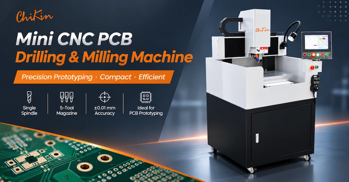
The CHIKIN CNC Mini CK-01R is a single-spindle PCB drilling and routing machine with a published 60,000 RPM water-cooled spindle, five-position tool magazine, tool-length detection, and ±0.01mm positioning and repeatability specifications.
For PCB prototyping laboratories and small-batch manufacturers, the main purchasing question is whether the machine can produce correctly positioned holes and finished contours without introducing unacceptable errors during tool changes or board handling.
This guide explains how to plan a drill-to-route workflow, protect the machining datum, verify tool-length settings, and evaluate first-article quality.
Key Takeaways
-
One controlled setup: Drilling and routing can share the same workpiece reference when the fixture and CNC program are configured correctly.
-
Five-tool configuration: The supplied Mini CK-01R specification lists a five-position tool magazine for compatible drilling and routing tools.
-
Tool-length detection: Included in the specification, this function supports tool setup verification but does not independently guarantee finished-part accuracy.
-
Published precision: Positioning and repeatability are both listed as ±0.01mm, subject to machine-specific verification.
-
Quality priority: Hole-to-outline accuracy must be measured on actual finished panels.
-
Procurement recommendation: Confirm the exact machine configuration, workholding system, tool-change functions, and acceptance criteria before placing an order.
1. What Is PCB Drill-to-Route Alignment?
PCB drill-to-route alignment is the positional relationship between the holes drilled in a circuit board and the outlines, slots, or profiles created during routing.
In printed circuit board manufacturing, drilling and routing often serve different purposes.
Drilling creates holes for components, mounting points, vias, or other specified features.
Routing removes material along programmed paths to create board outlines, internal openings, slots, or other mechanical features.
Both processes must follow compatible coordinate references.
Why Does Hole-to-Outline Accuracy Matter?
A PCB may have individually acceptable holes and a correctly shaped outline but still fail mechanical assembly if the two feature groups are misaligned.
Potential problems include:
-
Mounting holes positioned incorrectly relative to the board edge.
-
Connector openings that do not match enclosure geometry.
-
Uneven edge clearance around specified features.
-
Slots displaced relative to mounting points.
-
Difficulty installing the board into an assembly fixture.
-
Rework caused by inconsistent positioning between operations.
The manufacturing objective is to keep the hole pattern and routed geometry within the tolerances established by the approved PCB drawing.
What Causes Drill-to-Route Misalignment?
| Potential Cause | Effect on Finished PCB | Recommended Check |
|---|---|---|
| Different program datums | Hole pattern and outline shift | Compare coordinate origins |
| Workpiece movement | Positional variation | Inspect clamping and support |
| Incorrect tool offset | Dimensional or depth errors | Verify tool compensation |
| Wrong routing-tool diameter | Incorrect finished contours | Inspect tool and program |
| Fixture repositioning | Registration differences | Check locating references |
| Spindle runout | Hole or contour variation | Measure the tool-holding system |
| Material deformation | Board geometry changes | Inspect flatness and laminate condition |
A single-machine workflow can reduce certain transfer-related risks, but it cannot eliminate every cause of machining error.
2. CHIKIN CNC Mini CK-01R: Technical Specifications
CHIKIN CNC provides PCB drilling, routing, and related manufacturing equipment.
The Mini 1 Spindle PCB Routing and Drilling Machine is presented as a compact enclosed CNC system for prototyping and small-batch applications.
The supplied MINI CK-01R specification describes a single-spindle configuration with a water-cooled spindle, CNC-controlled axes, tool magazine, and tool-length detection.
Mini CK-01R Specification Table
| Technical Parameter | Supplied Specification |
|---|---|
| Model | MINI CK-01R |
| Number of spindles | 1 |
| Maximum spindle speed | 60,000 RPM |
| Spindle power | 1.8kW |
| Spindle cooling | Water cooling |
| X/Y/Z linear rails | Taiwan |
| X/Y/Z ballscrews | Taiwan |
| Maximum X/Y travel speed | 12m/min |
| Maximum Z travel speed | 12m/min |
| Repeatability | ±0.01mm |
| Positioning accuracy | ±0.01mm |
| Worktable dimensions | 350 × 350mm |
| Machine body material | Cast iron |
| CNC system | CHIKIN CNC |
| Operating language | Chinese / English |
| Tool magazine capacity | 5 positions |
| Drilling tool diameter | 0.5–6.35mm |
| Routing tool diameter | 0.8–3.175mm |
| Tool-length detection | Included |
| Spindle overload protection | Optional |
| Spindle overheat protection | Optional |
| Air supply | 0.6–0.8MPa |
| Listed air consumption | 30L/min |
| Power supply | Single-phase 220V / 50Hz |
| Listed power requirement | 2kW |
| Machine dimensions | 780 × 900 × 1700mm |
| Machine weight | Approximately 500kg |
| Installation temperature | 18–23°C |
| Installation humidity | 45–65% |
These specifications apply to the MINI CK-01R configuration supplied for this article. Other public CK-01R materials describe different spindle power, magazine capacity, and table dimensions. Confirm the exact configuration in writing before ordering.
What Should Buyers Verify?
The 350 × 350mm measurement describes the published worktable dimensions. It should not automatically be treated as the complete usable drilling and routing envelope.
The exact travel limits, spindle-to-table clearance, fixture compatibility, and automatic tool-change sequence should be verified against the ordered machine.
The listed ±0.01mm positioning and repeatability specifications also require defined test conditions.
3. Why Perform PCB Drilling and Routing in One Setup?
In traditional multi-machine processing, a PCB panel may be drilled on one machine and then transferred to a separate routing machine.
This requires the workpiece to be positioned again.
If the two operations use different fixtures or coordinate references, additional registration variation may occur.
A suitable single-spindle drilling and routing machine can execute both operations using one controlled CNC coordinate system.
Single Setup vs Separate Machines
| Evaluation | Single-Setup Drilling and Routing | Separate Drilling and Routing |
|---|---|---|
| Workpiece transfer | Potentially reduced | Usually required |
| Datum coordination | Shared setup possible | Separate setups require alignment |
| Tool changes | Required between different operations | Depends on each machine |
| Production flexibility | Useful for mixed operations | Processes can run independently |
| Maximum throughput | Limited by available spindle capacity | Depends on equipment arrangement |
| Main risk | Tool and fixture control | Transfer and registration variation |
When Is a Single-Setup Process Worth Considering?
A compact system can be relevant when a factory produces prototypes or short runs containing several drilled and routed features.
The main value is repeatable processing with fewer opportunities for repositioning errors.
However, high-volume factories may prefer separate or multi-spindle equipment when throughput is the dominant requirement.
For a broader overview, see CHIKIN's PCB CNC Drilling and Routing Machine Guide.
4. How to Establish a Common Drilling and Routing Datum
A datum is the reference used to define feature positions.
For drill-to-route processing, the drilling program and routing program should use compatible origins and orientation references.
Recommended Datum-Control Workflow
Step 1 — Review Engineering Files
Verify that drilling coordinates and routing paths use the approved design revision and coordinate system.
Step 2 — Define the Workpiece Origin
Establish the intended machine reference according to the approved fixture and program.
Step 3 — Secure the Panel
Use a workholding arrangement suitable for the board size, thickness, and planned machining operations.
Step 4 — Perform Drilling
Execute the approved hole pattern using the required tools and machining parameters.
Step 5 — Verify Tool Setup
Confirm the appropriate tool-length and diameter compensation before routing.
Step 6 — Perform Routing
Process the required profiles while maintaining the approved workpiece reference.
Step 7 — Inspect Finished Geometry
Measure the completed hole-to-outline relationships.
This workflow assumes that the installed tooling and control system support the intended process sequence.
Why Should the Board Remain Secure?
Even when both programs use the same coordinate origin, physical workpiece movement can invalidate the relationship.
A panel that shifts during routing may produce a finished contour displaced from the previously drilled holes.
Workholding and cutting conditions should therefore be qualified together.
5. How Should the Five-Tool Magazine Be Organized?
The supplied Mini CK-01R specification identifies a five-position tool magazine.
For a combined drilling and routing job, magazine planning should reflect the actual tools required by the manufacturing program.
Illustrative Five-Tool Setup
| Tool Position | Example Tool | Intended Operation |
|---|---|---|
| T1 | Small-diameter drill | Fine hole pattern |
| T2 | Medium-diameter drill | Additional required holes |
| T3 | Larger drill | Mounting or tooling holes |
| T4 | Small routing cutter | Narrow slots or internal profiles |
| T5 | Routing cutter | Board outline processing |
This table illustrates possible tool allocation. Actual tool sizes, magazine interfaces, and compatible operations must be confirmed.
Why Does Tool Sequencing Matter?
An inefficient sequence can create unnecessary changes between tools.
For example, repeatedly alternating between a drilling tool and a routing cutter may increase non-cutting time.
Where the design and process permit, operations can be grouped by tool to improve workflow consistency.
However, the processing order should be selected according to quality and workholding requirements—not tool-change count alone.
Is Automatic Tool Change Confirmed?
The supplied miniature-machine table establishes five tool positions and included tool-length detection.
The exact automatic tool-change mechanism and program sequence should be confirmed for this configuration.
Buyers should not assume every CK-01R variant uses the same magazine or tool-changing system.
6. What Does Tool-Length Detection Actually Control?
Tool-length detection helps establish a reference associated with the installed cutting tool.
This is relevant because different drills and routing cutters may have different overall lengths and cutting projections.
Incorrect tool-length compensation can affect the actual vertical position of the cutter.
Tool-Length Detection vs Tool-Diameter Compensation
| Function | Main Purpose | Potential Error |
|---|---|---|
| Tool-length detection | Establish vertical tool reference | Incorrect drilling or routing depth |
| Tool-diameter compensation | Account for cutter diameter | Incorrect profile dimensions |
| Workpiece datum | Establish part coordinate reference | Shifted feature locations |
| Spindle runout inspection | Evaluate tool rotation consistency | Hole and edge variation |
| Tool-condition inspection | Identify unsuitable cutting tools | Burrs, breakage or poor finish |
Does Tool-Length Detection Automatically Prevent Alignment Errors?
No.
Tool-length detection primarily concerns the tool's axial position.
It does not independently correct incorrect X/Y coordinates, worn cutting edges, fixture movement, or unsuitable cutter diameter.
A complete process should verify these factors separately.
Why Is Tool Verification Important for Small PCB Cutters?
Small-diameter drilling and routing tools can be sensitive to runout, vibration, and inappropriate cutting conditions.
The supplied CK-01R specification lists water cooling and tool-length detection, but it does not establish automatic broken-tool detection for this miniature configuration.
Factories should confirm which monitoring functions are included and define suitable inspection procedures.
For tool-holding maintenance, CHIKIN's PCB Spindle Collet Cleaning Guide explains how contamination, wear, and runout can affect drilling and routing quality.
7. How Does Fixture Design Affect Hole-to-Outline Consistency?
Fixture design determines how the PCB is supported and located during machining.
A poorly designed fixture can allow movement even when the CNC motion system performs correctly.
Workholding Considerations
| Fixture Factor | Potential Impact | Buyer Verification |
|---|---|---|
| Board support | Bending or vibration | Check flatness and stability |
| Locating features | Coordinate consistency | Confirm approved datums |
| Clamping force | Board distortion | Inspect contact areas |
| Router clearance | Tool interference | Review toolpaths |
| Cutting tabs | Part retention | Check tab placement |
| Vacuum holding | Workpiece security | Verify actual holding performance |
| Fixture height | Reduced tool clearance | Check spindle and holder access |
Why Is Operation Order Important?
During outline routing, the cutting process may progressively separate the finished PCB from surrounding material.
If the board loses support before the final cut is complete, it may move.
This can damage the edge or change the position of the remaining material.
A qualified process should use appropriate fixtures, tabs, or other approved retention methods where necessary.
For small PCB prototypes, maintaining support until all critical operations are finished can be as important as the machine's nominal accuracy.
8. Which PCB Materials and Tools Require Separate Validation?
The Mini CK-01R is presented for PCB prototyping, drilling, routing, and suitable light machining operations.
Actual material compatibility depends on the installed spindle, cutters, fixture, and processing conditions.
Material Qualification Matrix
| Material | Processing Concern | Validation Requirement |
|---|---|---|
| FR4 | Abrasive glass-fiber reinforcement | Tool wear and edge quality |
| Multilayer rigid PCB | Copper and laminate construction | Hole and outline integrity |
| Thin rigid PCB | Flexing during machining | Support and clamping |
| Aluminum-based PCB | Metal cutting forces and burrs | Suitable tools and parameters |
| Engineering fixtures | Material-specific machining | Spindle and tooling compatibility |
What Are the Published Tool Diameter Ranges?
The supplied specification lists:
Drilling tools: 0.5–6.35mm
Routing tools: 0.8–3.175mm
These ranges describe tool-diameter compatibility in the supplied configuration.
They do not guarantee that every tool within the range can process every material or depth.
How Can Buyers Reduce Tool-Related Defects?
Verify tool geometry, shank compatibility, runout, and actual material suitability.
Use cutting parameters approved for the specific material and tool.
Inspect representative finished holes and routed edges before releasing a production batch.
9. How to Perform a Drill-to-Route First-Article Inspection
First-Article Inspection (FAI) verifies whether an initial completed workpiece meets the approved requirements before larger production begins.
For combined drilling and routing, inspection should focus on the relationship between the two operations.
Recommended FAI Checklist
| Inspection Item | Acceptance Requirement |
|---|---|
| Hole diameter | Meets drawing tolerance |
| Hole center position | Meets approved datum reference |
| Hole-to-outline distance | Matches the required geometry |
| Slot dimensions | Conforms to engineering drawing |
| Routed contour | Meets dimensional tolerance |
| Board edge quality | No unacceptable burrs or breakout |
| Laminate integrity | No unacceptable cracks or damage |
| Tool-length setup | Approved tool reference verified |
| Workpiece stability | No unacceptable movement |
| Repeatability | Consistent results across samples |
Practical Inspection Procedure
First, confirm the approved board design and CNC programs.
Second, check the workpiece fixture and installed tool set.
Third, drill the required holes.
Fourth, process the relevant routed features using the same approved datum system.
Fifth, measure the finished hole positions relative to the routed outline.
Sixth, repeat the operation on additional representative boards.
Finally, document the results and investigate any features outside the agreed tolerance.
What Is the Most Important Measurement?
For this application, one critical result is the relative position of drilled holes to routed features.
A board may satisfy individual drilling and routing checks while still failing the required relationship between those features.
The inspection plan should therefore include the hole-to-outline dimensions that matter to the final assembly.
10. How to Measure Real Production Efficiency
A compact CNC drilling and routing machine should be evaluated by accepted output rather than nominal spindle speed.
The complete process includes loading, alignment, drilling, tool changes, routing, inspection, and unloading.
Production Cycle Calculation
Total Cycle Time = Loading + Setup + Drilling + Tool Changes + Routing + Inspection + Unloading
For repeated production, the factory can calculate:
Accepted Panels per Hour = Completed Panels per Hour × Acceptance Rate
What Affects Actual Throughput?
| Factor | Production Impact |
|---|---|
| Number of holes | Drilling workload |
| Hole diameters | Tool requirements |
| Routed outline length | Cutting time |
| Number of tools | Tool-change requirements |
| Board thickness | Cutting conditions |
| Workholding | Setup and handling |
| Tool wear | Replacement frequency |
| Inspection | Required quality-control time |
When Is a Single-Spindle Machine Economical?
A single-spindle machine may be attractive when a factory values flexible processing, limited space, and frequent product changes.
For higher-volume production, multiple spindles may reduce bottlenecks depending on the application.
The correct equipment choice should consider actual demand, manufacturing complexity, and accepted output.
11. Mini CK-01R Factory Acceptance Test: What Should Buyers Verify?
A Factory Acceptance Test (FAT) should demonstrate whether the specified equipment can complete the intended PCB machining process.
For the Mini CK-01R, the FAT should verify both individual operations and drill-to-route alignment.
Mini CK-01R FAT Checklist
| Test Item | Recommended Verification |
|---|---|
| Machine configuration | Confirm MINI CK-01R variant |
| Spindle | Verify 1.8kW / 60,000 RPM specification |
| Worktable | Confirm 350 × 350mm dimensions |
| Tool magazine | Verify five-position capacity |
| Tool-length detection | Demonstrate actual function |
| Drilling tools | Test required diameters |
| Routing tools | Test required cutter sizes |
| Positioning accuracy | Review defined measurement results |
| Repeatability | Test multiple processing cycles |
| Drill-to-route alignment | Measure finished feature relationships |
| Workholding | Check board stability |
| Cooling | Verify installed water-cooling system |
| Extraction | Confirm required dust-control arrangement |
| Safety | Verify guarding and emergency controls |
| Documentation | Review manuals and inspection reports |
Recommended Sample Qualification
Use actual PCB materials and production drawings.
Prepare a machining program containing representative drilling and routing operations.
Process the sample using the approved tool sequence.
Measure the finished holes, profiles, and critical hole-to-outline distances.
Repeat the test using the same setup to evaluate consistency.
The supplier and buyer should agree on acceptance criteria before equipment approval.
Why Is Configuration Verification Important?
Other public CK-01R information describes different spindle power, tool-magazine capacity, and machine construction.
Therefore, the quotation should specify the exact MINI CK-01R variant and its installed components.
For overseas buyers, a model name alone is insufficient when different configurations may share similar naming.
12. Installation, Maintenance, and Safety Considerations
The supplied Mini CK-01R configuration has published dimensions of 780 × 900 × 1700mm and a weight of approximately 500kg.
These values are useful for preliminary factory planning.
Installation Requirements
| Requirement | Supplied Value |
|---|---|
| Electrical supply | Single-phase 220V / 50Hz |
| Listed machine power | 2kW |
| Air pressure | 0.6–0.8MPa |
| Listed air consumption | 30L/min |
| Ambient temperature | 18–23°C |
| Ambient humidity | 45–65% |
| Machine weight | Approximately 500kg |
The datasheet also lists dust-related parameters. Buyers should confirm the required extraction airflow, vacuum pressure, connection dimensions, and whether extraction equipment is included.
Why Does Maintenance Affect Alignment?
A poorly maintained spindle, tool holder, or fixture can introduce processing variation.
Maintenance planning should cover tool condition, spindle holding, cooling, workholding, and relevant machine positioning checks.
Operators should follow the manufacturer's safety and maintenance procedures, including safe isolation before working on moving or rotating components.
An enclosed machine should not automatically be assumed compliant with a particular machinery safety standard without supporting documentation.
13. Technical RFQ Checklist for Overseas Buyers
A detailed Request for Quotation helps the supplier determine whether the Mini CK-01R configuration can process the intended PCB designs.
| Information Required | What to Provide |
|---|---|
| PCB material | FR4, multilayer or other specified material |
| Board dimensions | Maximum length, width, and thickness |
| Hole pattern | Drilling file and required diameters |
| Routing geometry | Outline, slots, and internal features |
| Registration requirement | Hole-to-outline tolerance |
| Tool quantities | Required drill and routing tools |
| Tool dimensions | Cutting diameter and shank information |
| Workholding | Preferred fixture or board support |
| Production volume | Panels per batch or shift |
| Quality inspection | FAI and FAT requirements |
| Factory utilities | Electrical, air, cooling, and extraction |
| Commercial requirements | Quantity, delivery destination, and support scope |
Request a Mini CK-01R Technical Evaluation
CHIKIN CNC supplies PCB drilling, routing, and related manufacturing equipment.
The Mini CK-01R is relevant to PCB manufacturers looking for a compact, single-spindle platform for combined machining operations.
Before purchasing, confirm the exact supplied configuration, tool-magazine functions, worktable and usable travel, tool-length detection procedure, and material compatibility.
Review the CHIKIN CNC Mini PCB Drilling and Routing Machine.
Contact CHIKIN CNC for a Mini CK-01R Sample Processing Review and Quotation.
Provide your PCB drilling files, routing outlines, material specifications, and required hole-to-outline tolerance for a more useful technical assessment.
14. Frequently Asked Questions About Mini PCB Drilling and Routing Machines
1. What is PCB drill-to-route alignment?
It is the positional relationship between drilled holes and routed board features. Proper alignment helps ensure that completed boards conform to mechanical drawings and fit their intended assemblies.
2. Can a single-spindle machine perform both drilling and routing?
Yes, when the spindle, tooling, controller, and machine configuration support the required operations. The Mini CK-01R is specified for compatible drilling and routing tools.
3. What is the tool-magazine capacity of the Mini CK-01R?
The supplied MINI CK-01R specification lists five tool positions. Other CK-01R configurations may differ, so the exact quoted variant should be confirmed.
4. What spindle does the Mini CK-01R use?
The supplied configuration lists a 1.8kW, 60,000 RPM water-cooled spindle.
5. What is the worktable size?
The published table dimensions are 350 × 350mm. The actual usable machining envelope and fixture clearance require separate confirmation.
6. Does tool-length detection guarantee accurate routing depth?
No. It supports tool setup measurement, but actual routing depth also depends on the workpiece datum, tool offset, fixture, machine movement, and processing conditions.
7. What drilling and routing tool sizes are supported?
The supplied specification lists drilling tools from 0.5–6.35mm and routing tools from 0.8–3.175mm, subject to actual holder and application compatibility.
8. Can drilling and routing be completed without removing the board?
A suitable CNC workflow may perform both operations using one controlled workpiece setup. Actual feasibility depends on the fixture, tool changes, program, and required machining geometry.
9. How should manufacturers inspect drill-to-route accuracy?
Measure finished hole positions relative to the routed board outline, slots, and other specified features using the approved drawing datums and calibrated inspection equipment.
10. How can overseas buyers request a Mini CK-01R quotation?
Provide the PCB material, board dimensions, drilling files, routing geometry, tooling requirements, hole-to-outline tolerances, and expected production volume. Request confirmation of the exact machine variant and representative sample processing.
Conclusion
Accurate PCB drill-to-route alignment is essential when a manufacturing process requires drilled holes and routed board features to maintain a controlled positional relationship.
The CHIKIN CNC Mini CK-01R offers a published single-spindle configuration with a 60,000 RPM water-cooled spindle, five-position tool magazine, tool-length detection, and ±0.01mm positioning and repeatability specifications.
These characteristics provide a basis for evaluating a compact CNC workflow that combines drilling and routing within a controlled setup.
However, successful PCB production depends on more than machine specifications.
The workpiece datum, fixture stability, tool condition, tool offsets, processing sequence, and finished-part inspection all influence the final result.
For PCB prototype laboratories and small-batch manufacturers, the most valuable purchasing approach is to verify actual hole-to-outline accuracy using representative production samples.
A documented first-article inspection and Factory Acceptance Test can help determine whether the selected machine configuration meets the required manufacturing conditions.
Contact CHIKIN CNC for a Mini CK-01R Technical Evaluation and Quotation and share your PCB drawings, drilling requirements, routing patterns, and production targets.
A CNC machine selected around the complete drill-to-route workflow can provide a stronger foundation for consistent, repeatable, and economical small-batch PCB manufacturing.