



TL;DR — Quick Answer
A PCB drill bit ring setting machine is used to install positioning collars onto compatible PCB drilling tools at a controlled location along the shank. Correctly positioned rings help standardize tool protrusion and support consistent handling in CNC drilling systems designed for ringed tools.
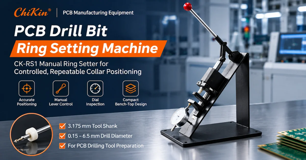
The CHIKIN CNC CK-RS1 is a manual ring-setting machine designed for PCB drill bits with a 3.175mm shank and a published cutting-diameter compatibility range of 0.15–6.5mm. Its compact lever-operated structure makes it relevant to PCB tool preparation, drill maintenance workshops, and factories handling small batches of precision carbide tools.
For buyers, the most important evaluation criteria are collar-position repeatability, tool protection, fixture compatibility, and inspection procedures—not the machine's weight or appearance alone.
Key Takeaways
-
Application: The CK-RS1 is intended for setting rings on PCB drill bits, rather than general jewelry or component assembly.
-
Tool compatibility: Its published specification identifies a 3.175mm tool shank and a 0.15–6.5mm drill diameter range.
-
Quality requirement: The ring position should be measured against the datum and tolerance specified by the intended drilling system.
-
Tool protection: Micro-drills require careful handling because excessive pressing force or incorrect support can damage fragile carbide tools.
-
Procurement decision: Verify actual ring-setting consistency, tooling dimensions, inspection capability, and availability before ordering.
1. Why Does Stop-Ring Position Matter in PCB Drilling?
PCB manufacturing relies on accurate and repeatable drilling operations.
In production environments, drilling tools may be changed repeatedly as different hole diameters, materials, and machining programs are processed.
A positioning ring, also called a depth-setting ring or drill collar, provides a defined reference on a compatible cutting tool.
When properly installed and used with an appropriate tool-holding arrangement, the ring helps establish the tool's protrusion relative to a defined seating surface.
This is particularly relevant to CNC machines that use ringed tools in compatible tool holders or automatic tool-changing systems.
What Happens When Ring Position Varies?
An incorrectly positioned ring can introduce differences in tool seating or protrusion.
Depending on the machine design, this may create problems involving tool handling, height compensation, or interference with the intended tool-management process.
Potential consequences include:
-
Inconsistent tool protrusion.
-
Incorrect seating in compatible tool holders.
-
Additional tool-length adjustment.
-
Problems during automatic tool changing.
-
Unnecessary downtime during tool preparation.
-
Damage to delicate micro-drills during installation.
Important: A positioning ring does not independently guarantee drilling depth or finished-hole accuracy.
The CNC machine's control program, spindle condition, tool-length calibration, fixture setup, and drilling parameters remain essential.
For manufacturers operating automated PCB drilling equipment, correct ring placement should be treated as part of the overall tooling preparation process.
2. How Does a PCB Drill Ring Setting Machine Work?
A manual PCB ring setting machine provides a guided method for positioning and pressing a collar onto a drill shank.
The operator uses the machine's mechanical structure to control the installation process.
A typical procedure involves placing the appropriate ring and drill into compatible tooling, establishing the required position, applying controlled movement, and checking the resulting assembly.
The exact sequence depends on the ring material, drill dimensions, machine fixture, and installation instructions.
Why Use a Manual Lever Instead of Hand Pressing?
A guided lever arrangement can provide a more consistent mechanical path than unsupported hand installation.
It can also help maintain the alignment of the tool and ring when the correct fixture is used.
However, the existence of a lever does not establish a particular pressing force or installation tolerance.
Those capabilities must be confirmed through manufacturer documentation and sample testing.
Why Is Drill Protection Important?
PCB micro-drills are commonly manufactured from hard, wear-resistant carbide materials.
Although suitable for high-speed cutting, small carbide tools can be vulnerable to bending and impact damage during handling.
A ring-setting operation should avoid applying inappropriate force to the cutting tip or slender flute section.
The drill should be supported and positioned according to its approved tooling arrangement.
3. CHIKIN CNC CK-RS1: Technical Specifications
Shenzhen ChiKin Automation Equipment Co., Ltd. supplies PCB manufacturing equipment and related tooling solutions.
The CHIKIN CK-RS1 Ring Setting Machine is presented as a compact manual device for positioning rings on PCB drilling tools.
The supplied product images show a lever-operated mechanical structure with a rigid base, adjustable tooling area, and an analog dial indicator.
CK-RS1 Specification Table
| Technical Parameter | Published Specification |
|---|---|
| Model | CK-RS1 |
| Product type | Manual PCB ring setting machine |
| Main application | Setting rings |
| Intended tools | PCB drill bits |
| Applicable tool shank | 3.175mm |
| Applicable drill diameter | 0.15–6.5mm |
| Machine color | White / Black |
| Machine weight | 6kg |
| Overall dimensions | 150 × 250 × 320mm |
| Operation | Manual lever mechanism |
Specifications are based on the supplied product datasheet. Ring installation tolerance, pressing-force range, calibrated measurement capability, and supported collar dimensions have not been established by the supplied specification.
What Does the 3.175mm Shank Specification Mean?
The 3.175mm measurement refers to the drill's tool-holding shank, not its cutting diameter.
This distinction is important because a PCB drill may have a small cutting tip while retaining a larger standardized shank for machine compatibility.
The 0.15–6.5mm range describes the published applicable cutting-tool diameters.
It does not mean the machine can install every collar design across that range without an appropriate fixture.
Buyers should confirm the exact ring dimensions, drill geometry, and tool support requirements.
4. Which Buyers Should Consider the CK-RS1?
The CK-RS1 is most relevant to PCB manufacturing environments that need controlled preparation of ringed drilling tools.
Buyer and Application Matrix
| Buyer Type | Main Requirement | Potential CK-RS1 Application |
|---|---|---|
| PCB drilling workshop | Repeatable tool preparation | Manual ring installation |
| Multilayer PCB manufacturer | Reliable micro-drill handling | Preparing compatible collared drills |
| PCB tool maintenance team | Standardized tooling setup | Ring installation and inspection |
| PCB drill bit supplier | Tool preparation for customers | Application-specific collar positioning |
| Equipment maintenance department | Replacement tool preparation | Supporting compatible tool systems |
| PCB prototyping laboratory | Small-batch drill preparation | Bench-top manual operation |
| Industrial equipment distributor | Supporting tooling accessories | Product and configuration evaluation |
When Is a Manual Ring Setter Appropriate?
A manual ring setter is worth considering when tool preparation volumes are manageable and the operator can follow a controlled setup and inspection procedure.
It can also be useful when production teams frequently handle different drill sizes or require a compact tool-preparation station.
For factories processing very high volumes of drilling tools, semi-automatic or fully automatic ring-setting equipment may deserve comparison.
The correct choice depends on required output, ring-position tolerance, operator workload, and investment budget.
5. Manual vs Semi-Automatic vs Automatic Ring Setting Machines
Equipment selection should begin with the factory's actual tooling preparation requirements.
Ring Setting Technology Comparison
| Evaluation Factor | Manual Ring Setter | Semi-Automatic Ring Setter | Automatic Ring Setter |
|---|---|---|---|
| Operator involvement | High | Moderate | Lower |
| Tool loading | Typically manual | Depends on configuration | May be automated |
| Ring positioning | Fixture and operator dependent | Guided or assisted | Controlled by machine system |
| Production volume | Suitable for qualified lower-volume tasks | Medium-volume applications | Higher-volume applications |
| Flexibility | Depends on available fixtures | Model dependent | Automation and tooling dependent |
| Initial investment | Usually simpler equipment | Intermediate | Generally higher system investment |
| Inspection | May require separate verification | May include assisted checks | May support integrated inspection |
| Main selection concern | Repeatability and handling | Productivity and setup | Automation and traceability |
The CHIKIN CK-RS1 is positioned as a manual device.
Its suitability should be evaluated through controlled sample trials rather than assuming it offers the same automated functions as a larger ring-setting system.
When Does Automation Become Worthwhile?
Automation may be economically attractive when the cost of manual labor, inspection, and repeated setup becomes significant.
However, buyers should not assume automation eliminates the need for calibration or quality checks.
Even automated equipment requires appropriate tooling compatibility and a validated installation process.
6. How to Define the Correct PCB Drill Ring Setting Height
One of the most important technical questions is where the ring should be positioned along the drill shank.
There is no single ring-position measurement that should be applied automatically to every drilling system.
Different tool holders, drilling machines, and tooling conventions may require different reference dimensions.
Ring Position Reference
In many ringed-tool systems, the relevant dimension is measured between the drill tip and a specified face of the positioning ring.
The ring may provide a seating reference when the cutter is installed into a compatible machine.
However, the correct datum must come from the equipment's approved tooling specification.
Main Factors Affecting Ring Position
| Factor | Why It Matters |
|---|---|
| Drill overall length | Influences the available positioning range |
| Cutting-tip geometry | Affects the location of the measurement reference |
| Shank diameter | Determines collar interface compatibility |
| Collar dimensions | Affect installation and seating |
| Tool holder design | Determines the intended ring reference |
| Automatic tool changer | May require standardized tool presentation |
| Calibration method | Determines how ring position is verified |
| Tool condition | Damage can compromise installation or measurement |
Should Every PCB Drill Use the Same Ring Height?
Not necessarily.
A factory may use different tool families, holders, or equipment configurations.
Before installing rings, verify the ring-setting specification associated with the intended machine and tool.
Do not apply a ring-setting height taken from another machine without confirming compatibility.
This is particularly important when preparing tooling for multiple drilling-machine brands.
7. How to Set and Inspect Rings on PCB Drill Bits
A documented installation procedure helps reduce variation between operators and production batches.
The following is a recommended qualification workflow, not a manufacturer-certified CK-RS1 operating instruction.
Step 1: Confirm the Tool Specification
Verify the drill diameter, shank size, overall length, and approved collar type.
Check that the drill belongs to the specified tooling family.
Step 2: Inspect the Drill and Collar
Examine the drill for visible damage, contamination, or unsuitable geometry.
Confirm that the ring is free from cracks or other defects.
Step 3: Prepare the Ring Setter
Secure the machine on a suitable work surface.
Install the approved tool support and confirm the relevant positional adjustment.
Step 4: Establish the Setting Reference
Set the intended collar position according to the drilling system's approved specification.
Use the appropriate reference surface and measurement procedure.
Step 5: Install the Ring
Apply controlled lever movement using the approved setup.
Avoid unsupported lateral force or direct pressure on delicate cutting features.
Step 6: Measure the Completed Tool
Verify the ring position against the specified datum.
Inspect collar alignment and the condition of the drill.
Step 7: Record the Result
For controlled production, record the tool batch, ring specification, setting requirement, operator, and inspection result.
The machine's final operating instructions should define the exact installation sequence, permissible force, and safe handling procedure.
8. How to Verify Ring Position Accuracy and Tool Quality
The most useful acceptance test is not whether the lever moves smoothly.
It is whether the machine can repeatedly install rings within the tolerance required by the intended drilling system while keeping the tools undamaged.
Ring Setting Quality Checklist
| Inspection Item | Recommended Verification |
|---|---|
| Ring position | Measure against the required reference dimension |
| Position repeatability | Compare multiple prepared tools |
| Collar alignment | Check for visible tilt or incorrect seating |
| Ring retention | Verify against the approved retention requirement |
| Shank condition | Inspect for damage or deformation |
| Drill tip condition | Confirm no installation-related damage |
| Collar condition | Check for cracking or distortion |
| Tool compatibility | Test across required drill sizes |
| Measurement consistency | Use a suitable calibrated measuring device |
| Batch records | Maintain identification and inspection results |
Can the Dial Indicator Measure Ring Position?
The product image shows an analog dial indicator associated with the lower assembly.
However, the supplied specification does not confirm its measurement range, resolution, calibration method, or exact function.
Therefore, it should not be treated as a verified micrometer-level ring-position measuring system without further documentation.
Buyers should ask how the indicator is used and whether a separate inspection device is required.
Does the CK-RS1 Guarantee a Specific Tolerance?
No numerical ring-setting tolerance is provided in the supplied product data.
A production accuracy claim should only be published after obtaining a defined manufacturer specification or actual qualification results.
The acceptance tolerance should be agreed before purchase.
9. Common PCB Drill Ring Setting Problems and Solutions
Even a compact manual ring setter can affect downstream tool preparation if the process is poorly controlled.
Troubleshooting Matrix
| Problem | Possible Cause | Recommended Action |
|---|---|---|
| Incorrect collar height | Wrong setting or measurement datum | Verify the approved reference |
| Ring seated at an angle | Misalignment or unsuitable support | Check fixture geometry |
| Damaged drill tip | Incorrect force application | Review tool support and handling |
| Loose ring | Incorrect collar size or installation | Check ring and shank compatibility |
| Inconsistent results | Adjustment movement or operator variation | Repeat controlled qualification |
| Tool not accepted by machine | Incorrect collar position or size | Verify holder and magazine requirements |
| Inaccurate dial reading | Gauge setup or calibration issue | Confirm measuring method |
| Slow tool preparation | Frequent setup or manual handling | Review workflow and tool batching |
Why Can Ring Installation Affect Tool Change Reliability?
In compatible automatic tool-changing systems, the ring may serve as part of the tool's mechanical positioning arrangement.
If the installed collar does not match the required geometry, the tool may not sit as intended.
However, actual tool-change behavior depends on the complete machine and holder design.
For example, CHIKIN's CK-02D 2 Spindle PCB Drilling Machine and CK-04D 4 Spindle PCB Drilling Machine are equipped with automated tool-management features.
Their specific compatibility with CK-RS1-prepared ringed tools should be confirmed rather than assumed.
10. How Does the CK-RS1 Fit Into a PCB Drill Preparation Workflow?
The CK-RS1 should be considered part of the tooling preparation process rather than an independent PCB drilling machine.
A typical controlled workflow may include tool selection, incoming inspection, ring installation, position verification, storage, and release to production.
Example Workflow: Preparing Micro-Drills for Production
Tool identification: Select the required diameter and tool family.
Initial inspection: Verify the tool condition and dimensions.
Ring installation: Use an approved ring setter and compatible collar.
Position inspection: Measure the completed ring location.
Tool storage: Protect the drill tips and identify the approved tools.
Production release: Transfer qualified tools to the applicable drilling operation.
This type of workflow can help factories organize tooling preparation and reduce uncertainty during tool replacement.
Why Does Tool Preparation Matter in Multi-Spindle PCB Drilling?
Multi-spindle production environments may require many tools with different diameters.
Consistent tool preparation can simplify handling and support standardized loading practices.
However, tool ring setting should not be confused with finished-hole inspection or drilling-machine calibration.
Each process addresses a different source of manufacturing variation.
11. What Determines the Cost of Ring Setting Equipment?
A manual ring setter may require less automation infrastructure than a fully automatic installation system.
However, total ownership cost depends on more than the machine's purchase price.
Cost Evaluation Table
| Cost Factor | What Buyers Should Check |
|---|---|
| Machine price | Base equipment and included fixtures |
| Ring compatibility | Approved collar dimensions |
| Tooling accessories | Required adapters and setting fixtures |
| Measurement equipment | Whether separate verification tools are necessary |
| Labor | Average preparation time per tool |
| Rejected assemblies | Incorrect ring positions and damaged drills |
| Maintenance | Wear parts, adjustment and inspection |
| Production volume | Required number of prepared tools |
| Service support | Documentation and spare-part availability |
A useful factory metric is:
Ring Setting Cost per Accepted Tool = Total Ring-Setting Operating Cost ÷ Number of Accepted Prepared Tools
This provides a more meaningful comparison than machine price alone.
When Is a Manual Ring Setter Economical?
A compact manual system may be practical for smaller tooling batches, engineering workshops, or preparation stations where flexible handling is important.
If tool preparation volumes increase significantly, compare the cost of operator time and rejected assemblies with the investment required for greater automation.
The best decision depends on actual workload and acceptance results.
12. Factory Acceptance Test: How to Evaluate the CK-RS1 Before Purchasing
A technical trial should establish whether the CK-RS1 can prepare the buyer's real drill and collar combinations.
CK-RS1 FAT Checklist
| Test Item | Recommended Acceptance Method |
|---|---|
| Model identification | Confirm CK-RS1 |
| Drill shank | Verify 3.175mm compatibility |
| Cutting diameter range | Test required tool sizes within the published range |
| Ring compatibility | Confirm actual collar material and dimensions |
| Installation procedure | Demonstrate the approved setting process |
| Position accuracy | Compare against buyer-defined tolerance |
| Repeatability | Measure a representative sample batch |
| Tool condition | Inspect drill tips and shanks after installation |
| Ring integrity | Inspect for damage or incorrect seating |
| Operator usability | Assess loading, adjustment and handling |
| Measurement system | Verify gauge function and calibration requirements |
| Documentation | Confirm operating instructions and maintenance information |
A Practical Sample Testing Method
Provide representative drill bits and the intended positioning rings.
Select tools that cover the main sizes used by the factory, including the smallest relevant micro-drills.
Define the required ring position and acceptable tolerance before testing.
Complete repeated installations under controlled conditions and measure the resulting assemblies with an appropriate instrument.
Evaluate both dimensional consistency and possible tool damage.
The final report should record accepted tools, rejected assemblies, and the conditions under which the results were obtained.
This is more meaningful than relying on the published compatible diameter range alone.
13. What Should B2B Buyers Include in a CK-RS1 RFQ?
A complete request for quotation helps the supplier assess whether the standard CK-RS1 configuration fits the customer's tooling.
Technical RFQ Checklist
| Required Information | Buyer Details |
|---|---|
| Drill type | PCB micro-drill or other applicable tool |
| Cutting diameter | Minimum and maximum required sizes |
| Shank diameter | Confirm 3.175mm |
| Tool overall length | Actual drill dimensions |
| Ring dimensions | Inner diameter, outer diameter and thickness |
| Ring material | Plastic or other specified material |
| Required position | Reference dimension and datum |
| Position tolerance | Acceptable installation variation |
| Tool quantity | Average tools prepared per day or shift |
| Inspection requirements | Measurement method and sampling |
| Downstream machine | Drilling machine and tool-holder configuration |
| Commercial requirements | Quantity, delivery destination and service needs |
Can the CK-RS1 Be Customized?
Potential application-specific discussions may include adjustment fixtures, tool supports, measurement arrangements, or alternative collar compatibility.
However, these are engineering evaluation topics, not confirmed standard features or guaranteed customization services.
Before ordering, provide the actual drill and collar drawings so the supplier can review the requested configuration.
14. Why Consider CHIKIN CNC for PCB Tool Preparation Equipment?
CHIKIN CNC, operated by Shenzhen ChiKin Automation Equipment Co., Ltd., provides PCB drilling, routing, and related manufacturing equipment.
The CK-RS1 extends the equipment discussion beyond the drilling machine itself to the preparation of compatible cutting tools.
For PCB factories using precision carbide micro-drills, a controlled tooling workflow can be important for reliable production.
The main value of a technical supplier discussion is confirming the compatibility between drill dimensions, collars, preparation fixtures, and the intended machine.
Request a CK-RS1 Technical Review
If your factory needs a manual solution for PCB drill-ring installation, prepare the relevant tool sizes, collar drawings, and ring-position requirements.
Review the CHIKIN CK-RS1 Ring Setting Machine product page.
You can also explore the company's PCB manufacturing equipment portfolio for related drilling and routing machines.
Contact CHIKIN CNC for a CK-RS1 Configuration Review and Quotation.
Providing actual drill and collar specifications will support a more accurate compatibility assessment.
15. Frequently Asked Questions About PCB Drill Ring Setting Machines
1. What is a PCB drill ring setting machine used for?
It is used to install positioning rings on compatible PCB drill bits. These rings provide a defined reference on the tool for suitable drilling-machine holders or tool-changing arrangements.
2. Is the CK-RS1 used for jewelry ring setting?
No. The supplied CK-RS1 specification identifies PCB drill bits and positioning-ring installation as its intended application. It is not presented as a gemstone or jewelry ring-setting machine.
3. What shank diameter does the CK-RS1 support?
The published specification lists a 3.175mm shank diameter. Buyers should confirm the actual shank tolerance and ring dimensions used by their tooling.
4. What drill diameters are compatible with the CK-RS1?
The published applicable tool diameter range is 0.15–6.5mm. This refers to the cutting-tool diameter range, not the diameter of the shank onto which the ring is installed.
5. Does a positioning ring determine the drilling depth?
It can help establish a tool-length or seating reference in compatible systems, but drilling depth also depends on CNC programming, machine calibration, and the tool-holding configuration.
6. Can the CK-RS1 install rings on very small carbide drills?
Its listed tool range begins at 0.15mm. However, the smallest tools should be evaluated carefully to confirm that the fixture supports the drill without damaging the cutting section.
7. Does the CK-RS1 include a precision measuring system?
The product image shows an analog dial indicator, but the supplied technical specification does not establish its measuring range, resolution, or calibration capability. These should be verified with CHIKIN CNC.
8. How much does the CK-RS1 weigh?
The published weight is 6kg, with overall dimensions of 150 × 250 × 320mm. This makes it a compact manual machine intended for bench-top use.
9. How does a manual ring setter compare with an automatic model?
A manual setter requires more operator involvement, while automatic equipment may reduce handling time for larger workloads. The appropriate choice depends on volume, required tolerance, tool compatibility, and measured production performance.
10. What information should I send when requesting a CK-RS1 quotation?
Provide the drill shank diameter, cutting diameter range, tool overall length, positioning-ring dimensions, required ring location, tolerance, preparation volume, and intended PCB drilling machine.
Conclusion
Choosing the right PCB drill bit ring setting machine requires a clear understanding of drill dimensions, positioning-ring requirements, tooling protection, and inspection methods.
The CHIKIN CNC CK-RS1 provides a compact manual configuration intended for PCB drill bits with 3.175mm shanks and published cutting diameters of 0.15–6.5mm.
Its lever-operated structure and bench-top format make it relevant to tooling preparation tasks where controlled manual installation is appropriate.
However, successful equipment selection must go beyond the nominal compatible diameter range.
Buyers should confirm the correct ring-position reference, evaluate the actual collar and drill combination, inspect the completed assemblies, and verify repeatability against defined acceptance criteria.
The most reliable procurement approach is to qualify the machine using representative tooling before approving production use.
For PCB manufacturers seeking a dedicated ring-setting solution, CHIKIN CNC provides the CK-RS1 within its broader PCB manufacturing equipment portfolio.
Review the CK-RS1 Ring Setting Machine or contact CHIKIN CNC for an application-specific technical review and quotation.
Share your PCB drill sizes, positioning-ring specifications, intended machine configuration, and required setting accuracy to determine whether the CK-RS1 is suitable for your tooling preparation workflow.