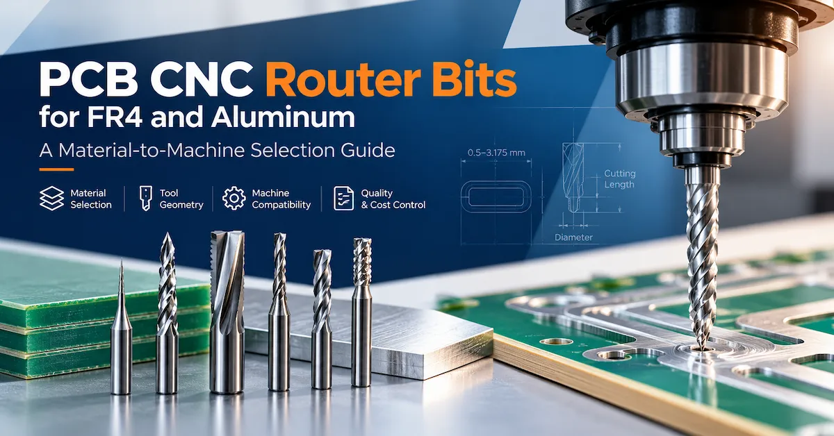




For PCB manufacturers, a small drill can have a large effect on production yield. Drill breakage, misplaced holes, rough hole walls, burrs, and inconsistent hole diameters can lead to rework, additional inspection, or rejected boards. These problems are particularly costly when factories process repeat orders or complex multilayer constructions.
This guide explains how to specify PCB CNC drill bits, compare tooling options, identify common drilling problems, and build a practical purchasing specification. For equipment selection, see the CHIKIN CNC PCB drilling machine buying guide.

1. What Are PCB CNC Drill Bits?
PCB CNC drill bits are precision cutting tools used with computer-controlled drilling equipment to produce holes in printed circuit boards. Depending on the board design, these holes may serve component leads, mounting hardware, mechanical alignment, or interconnection processes that continue through plating and other fabrication stages.
Many production PCB drills use cemented carbide because the material combines hardness with wear resistance. However, the correct tool also depends on diameter, flute design, cutting-edge condition, working length, laminate construction, and machine stability. Material alone does not guarantee hole quality.
Mechanical drilling should also be distinguished from laser drilling. Microvias made by laser systems involve different equipment and process controls; a conventional mechanical PCB drill bit should not be assumed suitable for every microvia application.
2. How to Choose the Correct PCB Drill Diameter
Start with the engineering drawing and the PCB fabrication requirements, not with the drill size currently in stock. The required mechanical drilling diameter and the final finished-hole diameter may differ, particularly for plated-through holes.
Check the hole chart and plating allowance
A finished plated hole is affected by the plating process. The drill diameter required before plating must therefore be agreed with the PCB process engineer or fabricator. Do not apply one universal allowance to every board: the correct value depends on the specified finished hole and the manufacturing process.
Consider thickness and tool length
A small-diameter drill has limited bending strength. As the effective unsupported length increases, the tool becomes more sensitive to runout, misalignment, lateral forces, and unsuitable cutting conditions. Confirm the board thickness, stack configuration, entry and backup materials, and the required working length before ordering.
| Specification | What buyers should confirm | Why it matters |
|---|---|---|
| Drill diameter | Required mechanical diameter and tolerance | Supports the correct finished-hole result |
| Finished-hole requirement | Plated or non-plated hole and applicable drawing notes | Prevents confusion between tool size and final opening |
| Working length | Board thickness, stack and engagement requirements | Reduces risk from unsuitable tool geometry |
| Shank diameter | Holder and spindle interface | Ensures secure, compatible tool holding |
| Tool geometry | Point, flute and cutting-edge specification | Influences chip evacuation and cutting behavior |
| Material | Laminate type and supplier's recommended tool | Supports application-specific wear control |
3. Select Drill Bits for FR4 and Multilayer PCB Production
FR4 circuit boards
FR4 combines epoxy resin and glass reinforcement. The glass fibers can be abrasive, while heat and debris must be managed during drilling. Tool condition, flute geometry, spindle stability, entry material, backup material, and cutting conditions all influence the result.
For FR4 production, evaluate hole diameter consistency, hole-wall condition, burr formation, tool breakage, and tool life under representative board thicknesses. A tool qualified on one construction should not automatically be treated as qualified for every FR4 grade or stack.
Multilayer PCBs
Multilayer boards add complexity because hole quality can affect later plating and electrical reliability. If defects appear, distinguish hole-wall roughness from resin smear and deformation of internal copper. These conditions may require different corrective actions.
Where the application is demanding, ask the tooling supplier to confirm the drill specification against the laminate, thickness, stack, and finished-hole requirement. Use sample drilling and documented inspection to verify the proposed selection.
Aluminum-based and other special constructions
Aluminum-based PCBs, rigid-flex boards, and other nonstandard constructions should be assessed individually. Do not transfer a drilling recipe from standard FR4 without checking the material, support arrangement, tool recommendation, and quality criteria.
4. Six Factors That Influence PCB Drill Bit Life
Small or slender tools may be more sensitive to bending, runout, and unstable cutting conditions.
Glass reinforcement, resin system, copper distribution, and thickness can change wear behavior.
Runout, contamination, poor insertion, or damaged holding components can shorten usable tool life.
Feed, spindle speed, stack arrangement, and chip evacuation must be qualified together.
Vibration, positioning problems, or board movement can damage tools and reduce hole consistency.
Unclear limits may allow deteriorating tools to remain in production or cause premature replacement.
There is no universal number of hits that applies to every PCB CNC drill bit. Tool life depends on the application and on the acceptance criteria used to define an acceptable hole. A reliable supplier should be able to explain the conditions behind any tool-life estimate.
5. How to Track PCB Drill Bit Life with Hit Count
In drilling, a hit count records the number of drilling operations performed by a tool under a defined process. It is a useful production metric, but it does not prove that every hole remains within specification.
To establish a useful tool-life baseline:
- Record the tool diameter, geometry, supplier, lot, and machine or spindle identification.
- Define the PCB material, thickness, stack arrangement, and drilling conditions.
- Set the required hole-quality and dimensional acceptance criteria.
- Record cumulative hits and inspect representative samples at planned intervals.
- Document the reason for tool removal, such as scheduled replacement, visible damage, a quality failure, or abnormal breakage.
- Review repeated runs before changing the approved hit-count limit.
For example, a tool removed after 8,000 hits because hole quality exceeded the agreed limit provides more useful information than a statement that the bit “lasted 8,000 hits.” The number is meaningful only when material, geometry, stack, conditions, and inspection criteria are also recorded.
6. Troubleshoot Common PCB Drilling Defects
| Observed issue | Possible tooling cause | Other checks |
|---|---|---|
| Frequent drill breakage | Damaged tool, unsuitable geometry, or excessive tool slenderness | Runout, feed, stack, board clamping and tool insertion |
| Inconsistent hole diameter | Tool wear or diameter variation | Spindle/holder condition, measurement method and positioning |
| Rough hole walls | Worn or unsuitable cutting geometry | Laminate, chip evacuation, cutting conditions and stack position |
| Burrs around holes | Tool condition or unsuitable cutting behavior | Material, entry/backup materials and drilling setup |
| Hole-position deviation | Tool deflection may contribute | Alignment, fixture, board movement and CNC positioning |
| Sudden change after tool replacement | New tool lot or specification may differ | Holder cleanliness, installation, material lot and recipe |
These are investigation paths, not automatic diagnoses. A rough hole wall does not by itself prove that the drill is worn. Compare a suspect tool with a verified tool of the same specification under controlled conditions. CHIKIN's article on rough PCB hole walls after drilling provides additional guidance on distinguishing defects and checking likely causes.
7. Verify Spindle, Collet and Machine Compatibility
A drill bit can have the correct cutting diameter but still be unsuitable for a particular machine. Buyers should confirm the shank diameter, holder or collet interface, overall length, tool-change arrangement, and applicable spindle limits.
Spindle runout and holder contamination deserve particular attention. If a fresh, correctly specified drill produces the same defect as the previous tool, inspect the machine and tool-holding system before ordering another batch. Repeatedly replacing tools without checking runout or clamping can increase consumable costs without resolving the root cause.
CHIKIN CNC publishes several PCB drilling and drilling/routing equipment configurations. Buyers can compare the CK-02D two-spindle PCB drilling machine and the CK-04D four-spindle PCB drilling machine as equipment starting points. Confirm the exact machine configuration and approved tooling interface before selecting a drill bit.
Some equipment configurations include tool-detection functions. Confirm which functions are included in the specific model and what they actually detect. Broken-tool detection, for example, should not automatically be treated as a direct measurement of gradual cutting-edge wear.
8. Calculate the Real Cost of PCB CNC Drill Bits
The purchase price per drill is only one part of the tooling cost. A lower-priced bit may require more frequent replacement or generate more defects, while a higher-priced tool may not deliver value if its performance is not demonstrated in the actual process.
A practical starting point is:
Tooling cost per accepted hole = relevant drill-tool expenditure ÷ number of accepted holes produced.
For a complete comparison, also consider tool-change labor, machine downtime, scrap, inspection, and the cost of investigating recurring defects. Compare candidate tools using the same board construction, hole specification, production conditions, and acceptance rules.
Do not compare a supplier's hit-count claim with another supplier's result unless the test conditions are sufficiently similar. Request the tool specification, test material, stack arrangement, process conditions, sample size, and reason for tool withdrawal.
9. PCB CNC Drill Bit Purchasing Checklist
Use this checklist when preparing an RFQ for drill bits or reviewing tooling requirements for a new PCB drilling machine.
- Drawing: Hole chart, required diameters, tolerances, plated/non-plated requirements, and finished-hole specifications.
- Material: FR4 or other construction, board thickness, layer count, and stack arrangement.
- Tool specification: Diameter, shank, point geometry, flute geometry, working length, and overall length.
- Machine: Model, spindle identification, holder/collet reference, and tool-change requirements.
- Process: Current cutting conditions, entry/backup materials, fixture arrangement, and production volume.
- Quality: Hole inspection method, acceptance limits, defect images, and sample-trial plan.
- Tool life: Expected hit-count range with stated test conditions and replacement criteria.
- Commercial details: Quantity, lot traceability, repeat-order needs, lead time, and documentation.
Where the website does not list an exact consumable SKU, confirm availability and compatibility directly rather than assuming that a machine product page represents a drill-bit catalogue. The verified CHIKIN CNC website focuses on PCB equipment and related products; specific drill-bit specifications and supply arrangements should be confirmed with the team.
10. Frequently Asked Questions
What are PCB CNC drill bits used for?
They are used with CNC drilling equipment to produce specified holes in printed circuit boards. Typical applications include component holes, mounting holes, alignment features, and mechanically drilled holes required by the PCB fabrication process.
Are carbide drill bits suitable for FR4 PCBs?
Carbide tools are widely used for PCB drilling, including many FR4 applications. The appropriate grade and geometry depend on the board construction, diameter, thickness, machine condition, and process requirements.
How many hits should a PCB CNC drill bit last?
There is no universal hit-count limit. Establish a qualified replacement interval using the actual material, tool specification, drilling conditions, and hole-quality acceptance criteria.
Why do PCB drill bits break frequently?
Possible causes include tool damage, unsuitable geometry, excessive runout, incorrect feed, poor chip evacuation, board movement, or an unsuitable stack arrangement. Investigate the complete process before assuming the tool itself is defective.
How can a buyer confirm drill-bit compatibility with a CNC machine?
Provide the machine and spindle model, holder or collet details, cutting diameter, shank diameter, tool length, board material, and required hole specifications. Request written confirmation for the exact configuration.
Does CHIKIN CNC list every PCB drill bit as a separate product?
The website's verified pages cover PCB drilling and drilling/routing equipment and related products. Buyers should contact CHIKIN CNC to confirm the availability and specification of a particular drill-bit consumable instead of assuming every tool is listed as an individual product.
Conclusion
Choosing the right PCB CNC drill bits requires more than matching a nominal diameter. PCB material, finished-hole requirements, working length, spindle runout, tool holding, drilling conditions, and documented hit-count limits all influence hole quality and production cost.
PCB manufacturers can reduce avoidable breakage and quality problems by qualifying the complete drilling process, tracking tool life under consistent conditions, and investigating defects before changing tooling specifications. For equipment planning, review CHIKIN CNC's PCB drilling and routing machines, or contact CHIKIN CNC with your hole chart, board material, machine model, and production requirements to discuss a suitable technical configuration.