



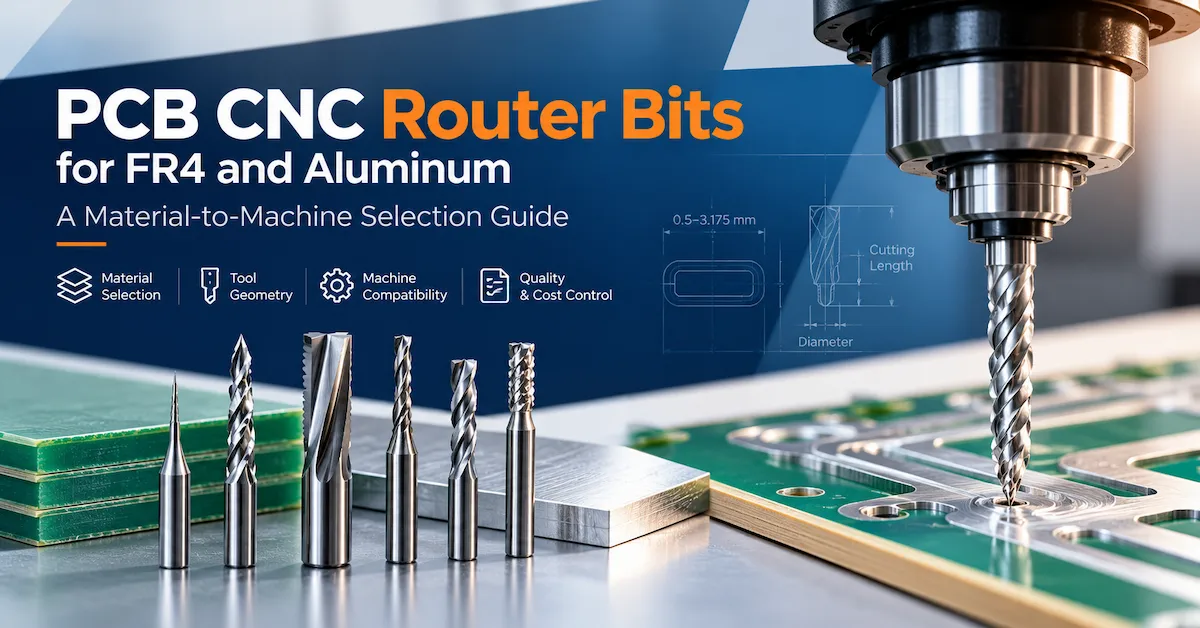
Selecting PCB CNC router bits is a manufacturing decision that directly influences board-edge quality, dimensional consistency, machine utilization, and tooling expenditure. A cutter that performs reliably on standard FR4 may be unsuitable for aluminum-core PCB processing, narrow internal slots, or thin rigid-flex constructions.
The best PCB router bit is the one whose cutting geometry, diameter, cutting length, tool material, and shank interface have been qualified for the actual board and CNC machine. There is no universal cutter that delivers optimal results across every PCB material.
For PCB fabrication factories, process engineers, and industrial purchasing managers, the practical selection process begins with three questions: What material is being machined? What geometric and quality requirements must be achieved? And can the machine hold and drive the selected tool under stable cutting conditions?
This guide explains how to answer those questions, compare tool types, validate candidate cutters, and prepare a technically complete procurement request.
1. What Are PCB CNC Router Bits?
PCB CNC router bits are precision rotary cutting tools used to machine printed circuit board outlines, slots, internal openings, and other mechanical features. They remove material along a programmed path while the CNC system controls tool movement.
Common applications include:
-
Routing external PCB profiles and panel outlines.
-
Producing non-plated slots and mechanical cutouts.
-
Machining irregular board shapes.
-
Processing selected multilayer and metal-core PCB constructions.
-
Separating suitable PCB panels by mechanical routing.
Industrial PCB router bits commonly use solid tungsten carbide because glass-fiber-reinforced laminates are abrasive and require cutting-edge hardness.
However, a router bit is not interchangeable with a conventional PCB drill.
A drill primarily produces holes through axial cutting. A router bit is designed to remove material during lateral movement. Differences in geometry, cutting forces, and tool design make this distinction important for spindle selection and process safety.
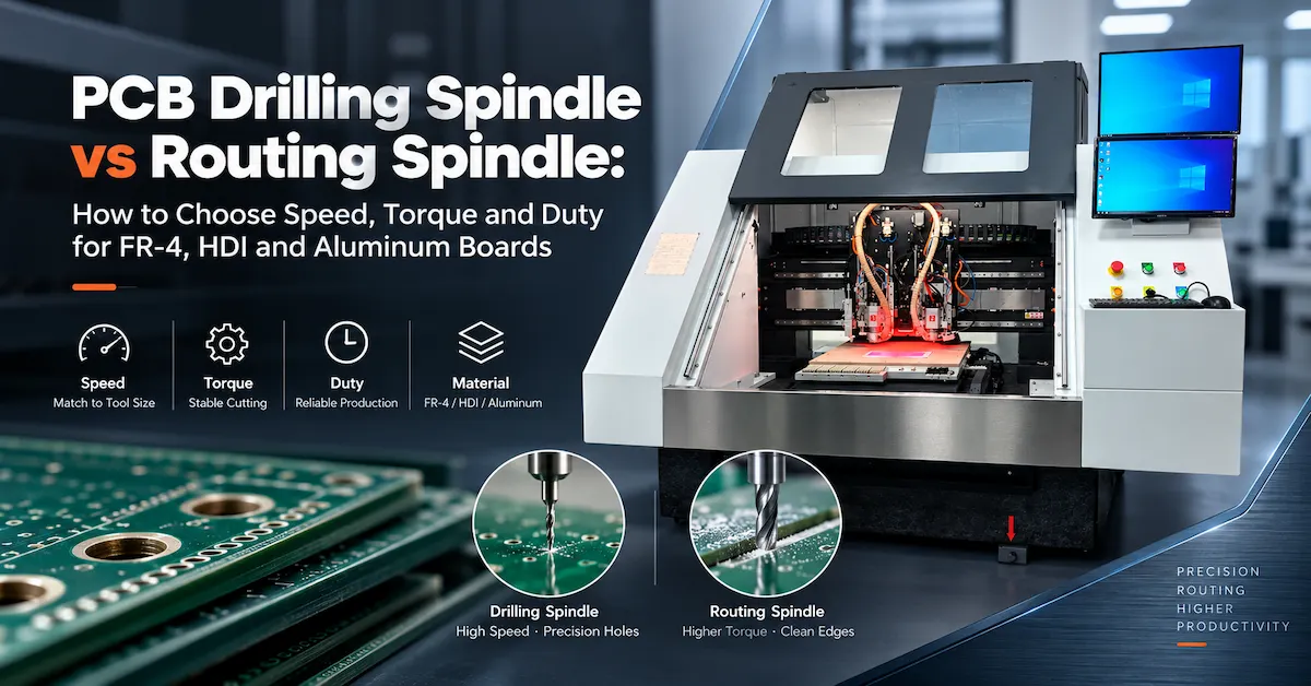
Manufacturers planning both operations should review equipment designed for PCB drilling and routing, rather than assuming a drilling-only machine supports every milling operation.
2. Who Needs Industrial PCB Router Bit Selection?
Tool selection matters most to PCB manufacturers operating repeated routing programs where dimensional consistency and production cost must remain predictable.
| Buyer or Application | Primary Requirement | Selection Priority |
|---|---|---|
| Rigid PCB fabrication factory | Repeatable outlines and slots | Carbide geometry, edge quality, dimensional control |
| Multilayer PCB manufacturer | Reliable machining near sensitive structures | Cutter diameter, vibration, board support |
| Aluminum PCB manufacturer | Controlled cutting through metal-core material | Non-ferrous geometry, chip evacuation, cutting load |
| PCB prototype workshop | Frequent product changes | Tool versatility, quick setup, accessible diameters |
| High-volume PCB factory | Repeatable output across production shifts | Tool consistency, qualified process window |
| Equipment procurement manager | Reliable tooling and machine compatibility | Specifications, sample validation, supplier documentation |
Not every application benefits from mechanical routing.
Extremely delicate flexible circuits, closely spaced components, unsupported thin features, or unusually demanding stress limits may require alternative processes. UV laser processing or other specialized separation methods should be evaluated when conventional mechanical cutting cannot meet the acceptance criteria.
3. How to Choose PCB CNC Router Bits for Different Materials
Material compatibility should be established before comparing cutter prices.
FR4, metal-core boards, and rigid-flex constructions differ in abrasiveness, stiffness, chip formation, and response to mechanical forces.
FR4 and Glass-Fiber-Reinforced Laminates
FR4 contains woven glass reinforcement within an epoxy-resin system.
During routing, the cutter repeatedly encounters glass fibers and resin. This creates abrasive wear and can contribute to fiber breakout, rough edges, or dimensional variation when the process is poorly matched.
Solid carbide cutters with geometries designed for glass-reinforced laminates are common candidates.
Diamond-cut or cross-cut router geometries are worth evaluating for routine FR4 contours and slotting. Their multiple cutting features can distribute cutting engagement, but the best result depends on the specific tool design and process.
Important: Diamond-cut describes a cutting geometry. It does not automatically mean the tool is made from polycrystalline diamond or has a diamond coating.
Aluminum-Core and Metal-Core PCBs
Aluminum-core PCBs create a different cutting challenge.
The metal layer can generate ductile chips, higher cutting forces, and material adhesion to unsuitable cutting edges. A cutter optimized for abrasive FR4 is not automatically suitable for aluminum.
Consider a manufacturer-recommended non-ferrous carbide end mill with appropriate flute geometry and chip clearance.
Evaluate aluminum thickness, surrounding dielectric layers, exposed copper, tool loading, and the risk of burr formation.
For metal-core boards, never select a router bit solely by PCB thickness. The composition of the complete stack is equally important.
Rigid-Flex and Thin PCB Constructions
Rigid-flex boards combine materials with different stiffness and cutting behavior.
Mechanical routing may be appropriate in selected rigid sections, but flexible regions can deform under cutting pressure.
Fixture support, tool geometry, cutting direction, and process qualification become especially important.
Where mechanical cutting introduces unacceptable movement or damage, a non-contact process may be more appropriate.
Material-to-Tool Selection Matrix
| PCB Material | Candidate Tool Direction | Main Processing Risk | Recommended Validation |
|---|---|---|---|
| Standard FR4 | Solid carbide diamond-cut or laminate-specific router | Glass-fiber breakout | Edge inspection and dimensional measurement |
| Thick multilayer FR4 | Rigid carbide tool with suitable cutting length | Deflection, heat, edge damage | Full-thickness routing sample |
| Aluminum-core PCB | Non-ferrous carbide cutting geometry | Metal burrs and chip adhesion | Burr inspection and spindle-load review |
| Copper-rich composite board | Tool qualified for the complete material stack | Copper smearing or delamination | Cross-material cutting evaluation |
| Thin rigid-flex PCB | Small, application-specific cutter | Flexing and unsupported edges | Fixture and deformation testing |
| Precision internal slots | Tool diameter matched to slot geometry | Oversized slots and corner interference | Slot-width and corner measurements |
These are candidate tooling directions, not guaranteed specifications. Final approval requires actual machining results.
4. PCB Router Bit Types: Which Cutting Geometry Should You Choose?
Cutting geometry influences chip formation, cutting resistance, edge finish, and suitability for a particular material.
Professional PCB tooling catalogs distinguish diamond-cut designs, chip-breaker tools, single-flute cutters, two-flute end mills, and specialty finishing cutters.
Router Bit Geometry Comparison
| Tool Type | Main Characteristic | Potential Application | Selection Consideration |
|---|---|---|---|
| Diamond-Cut Carbide Router | Multiple intersecting cutting features | FR4, glass-reinforced laminates | Evaluate fiber condition and dust evacuation |
| Chip-Breaker Router Bit | Interrupted or specialized cutting edges | Selected laminate-routing processes | Verify chip removal and finished edge |
| Single-Flute End Mill | Large chip space | Certain aluminum and non-ferrous operations | Check surface finish and cutting stability |
| Two-Flute End Mill | Two continuous cutting edges | Precision contouring and selected metals | Match chip load and material |
| Multi-Flute Finishing Tool | Additional cutting edges | Selected finishing applications | Check available chip clearance |
| Diamond-Coated or PCD Tool | Wear-resistant cutting technology | Certain high-abrasion production processes | Evaluate cost, geometry, and proven application life |
A two-flute cutter is not universally superior to a diamond-cut PCB router bit.
For example, an aluminum-core board may benefit from a different chip-removal strategy than abrasive FR4. Even two cutters with the same diameter can behave differently because of their cutting-edge geometry.
The correct comparison involves finished-board acceptance, not merely the number of flutes.
5. Technical Specifications to Confirm Before Ordering PCB CNC Router Bits
An industrial tooling request should describe more than cutter diameter.
PCB Router Bit Specification Checklist
| Specification | What to Confirm | Why It Matters |
|---|---|---|
| Cutting diameter | Nominal diameter and actual tolerance | Controls slot width and achievable internal geometry |
| Cutting length | Effective length of cutting edges | Determines material thickness engagement |
| Shank diameter | Exact shank size and tolerance | Must fit the approved collet or holder |
| Overall length | Total cutter length | Influences tool clearance and magazine compatibility |
| Flute geometry | Diamond-cut, single-flute, two-flute, specialty | Affects cutting behavior |
| Tool material | Solid carbide or other specified material | Influences stiffness and wear performance |
| Coating | Uncoated, diamond-coated, or other applicable finish | Must suit the actual material |
| Rotation direction | Required spindle and cutting direction | Prevents incorrect cutting engagement |
| Maximum permitted RPM | Tool supplier's operating limit | Supports safe operating conditions |
| Runout requirement | Permitted tool and assembled-holder deviation | Influences effective cutting diameter |
| Identification | Manufacturer code and production lot | Supports purchasing and quality traceability |
How Does Diameter Affect Slot Width?
A cutter must physically fit the feature being machined.
For a straight through-slot produced in one centerline pass, the nominal cut width is approximately the tool diameter. Actual results also depend on runout, deflection, tool wear, machine motion, and process settings.
For an internal 90-degree corner, a cylindrical cutter also leaves an internal corner radius. A nominal 1.0 mm cutter cannot create a perfectly sharp internal corner using ordinary mechanical routing.
Tool diameter should therefore be selected from the actual mechanical drawing rather than a general catalog recommendation.
Why Cutting Length Matters
The cutting length must suit the material and programmed engagement.
An excessively long exposed tool may be less rigid than necessary, especially at small diameters.
However, a cutter that is too short may leave unmachined material or create inappropriate contact outside the cutting section.
Compare usable cutting length, board thickness, fixture clearance, tool projection, and planned cutting passes.
6. How Do Spindle Speed, Feed Rate, and Tool Geometry Work Together?
Selecting the correct bit is only one part of a reliable PCB routing process.
Spindle speed, programmed feed rate, tool engagement, cutting depth, and board support influence how the cutter interacts with the material.
For a conventional fluted cutter, a simplified feed relationship is:
Feed Rate (mm/min) = Spindle Speed (RPM) × Number of Flutes × Feed per Tooth (mm/tooth)
This relationship helps engineers understand the interaction between rotational speed and chip load.
However, it should not be applied mechanically to every diamond-cut or burr-style cutter, where the cutting-edge arrangement differs from a conventional end mill.
For production setup:
-
Obtain the cutting tool manufacturer's recommended operating range.
-
Confirm the routing spindle and holder limitations.
-
Use the actual material and cutting engagement to establish trial settings.
-
Inspect finished edges, slots, and dimensional results.
-
Approve a stable operating window before increasing production output.
A machine rated for 60,000 RPM does not mean every router bit should operate at 60,000 RPM.
The appropriate speed must be validated against tool limitations, material, diameter, loading, and the machine configuration.
7. How to Qualify PCB Router Bits Before Batch Production
A low unit price has limited value if the tool produces unstable results.
Instead of approving cutters from catalog specifications alone, PCB factories should use a documented machining qualification procedure.
Step 1: Freeze the Application Requirements
Select a representative PCB containing the most relevant manufacturing challenges.
Record material construction, thickness, copper configuration, minimum slot width, outline dimensions, required edge finish, and production volume.
Step 2: Verify Physical Compatibility
Confirm that the tool shank fits the approved holder and that the exposed length provides adequate clearance.
Inspect the cutter and holder condition before installation.
Do not assume that all tools with the same cutting diameter have identical shank dimensions.
Step 3: Prepare a Controlled Test
Use a defined board sample, routing program, fixture, and dust-extraction arrangement.
Start with conservative, manufacturer-approved cutting conditions. Record spindle speed, feed, depth, tool identification, and machine location.
Step 4: Inspect Finished Components
Measure actual slot widths, contours, and critical features.
Examine edge damage, copper burrs, glass-fiber breakout, delamination, and deformation where relevant.
Evaluate multiple samples rather than relying on one acceptable board.
Step 5: Validate Repeatability
Repeat the test across suitable production conditions.
For multi-spindle equipment, consider whether different heads produce consistent results when using equivalent tooling.
Step 6: Approve the Tooling Specification
Once a candidate passes the agreed requirements, record its specification and qualified operating window.
Include acceptance limits, approved material combinations, inspection frequency, and the conditions that require requalification.
This converts a general purchasing item into a controlled production tool.
8. Quality Control and Applicable PCB Acceptance Standards
Tool suppliers and equipment manufacturers should not replace finished-product inspection with a claim of high machine accuracy.
A machine's positioning specification is different from the measured tolerance of a completed PCB profile.
For rigid printed boards, engineers can refer to applicable editions of IPC-A-600, Acceptability of Printed Boards, and IPC-6012, Qualification and Performance Specification for Rigid Printed Boards, together with customer drawings and contractual acceptance requirements.
These standards address printed-board acceptance and performance, rather than certifying a particular router-bit brand.
Inspection plans should consider:
| Quality Check | Practical Inspection Method | Typical Concern |
|---|---|---|
| Finished outline | Optical or calibrated dimensional measurement | Profile deviation |
| Slot width | Appropriate dimensional measuring equipment | Oversized or undersized openings |
| Board edge | Magnified visual inspection | Fiber pull-out or chipping |
| Copper edge | Optical inspection | Burrs or damaged conductors |
| Material integrity | Appropriate visual or cross-sectional examination | Delamination or cracking |
| Process consistency | Repeated sample measurements | Head-to-head or batch variation |
Acceptance limits must come from the applicable design and manufacturing requirements—not unsupported universal tolerances.
9. How Does CNC Machine Selection Affect Router Bit Performance?
Even a correctly specified carbide tool can perform poorly when the machine, spindle, fixture, or tool-management process is unsuitable.
For PCB factories considering equipment investment, CHIKIN CNC offers different drilling and routing configurations.
CHIKIN CNC Machine Comparison for Router Tooling
| Machine | Published Configuration | Tooling Consideration | Typical Buyer Requirement |
|---|---|---|---|
| CK-02R | 2 spindles, 60,000 RPM, 1.8 kW per spindle | Confirm tool-holding interface and consistent settings across heads | Mid-volume PCB routing |
| CK-04R | 4 spindles, 60,000 RPM, 1.8 kW per spindle | Coordinate tooling qualification across multiple spindles | Repeated higher-volume panel work |
| 1 Drill + 1 Route With CCD | Dedicated drilling and routing spindles, CCD positioning | Separate drilling and routing tool specifications | Combined processes with vision-assisted alignment |
The CCD-equipped machine's published routing tool diameter range is 0.5–3.175 mm. Tool-holder dimensions, cutting lengths, supported geometry, and final compatibility must still be confirmed for the selected configuration.
CHIKIN lists automatic tool changing, tool length measurement, tool diameter detection, and broken-tool detection among the features of these production-oriented platforms.
Such functions support a more controlled workflow, but they do not automatically measure cutting-edge wear or guarantee finished-board quality.
For plants comparing different configurations, the key question is not simply how many spindles are available. It is whether the proposed system can hold, drive, measure, and manage the qualified tool while meeting the required output.
10. What Are the Commercial Risks of Buying the Wrong Router Bits?
The least expensive PCB router bits are not necessarily the best purchasing decision.
A more meaningful evaluation considers accepted output and the additional operational costs created by the tooling choice.
Tooling Cost per Accepted Panel = Total Router Tooling Expenditure ÷ Number of Accepted Panels
For example, a lower-priced cutter may require more changes, additional inspections, or rework. A higher-priced alternative may deliver a better outcome when it produces consistent acceptable boards.
The calculation should distinguish estimated savings from results proven during qualification.
Other procurement risks include mismatched shank sizes, inconsistent cutter geometry between supplier lots, insufficient cutting length, poor packaging, missing lot identification, and inaccurate delivery commitments.
For wider equipment investment decisions, CHIKIN's PCB routing machine total-cost guide covers tooling, dust extraction, maintenance, and other operating-cost factors.
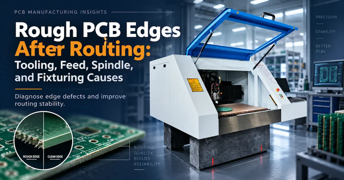
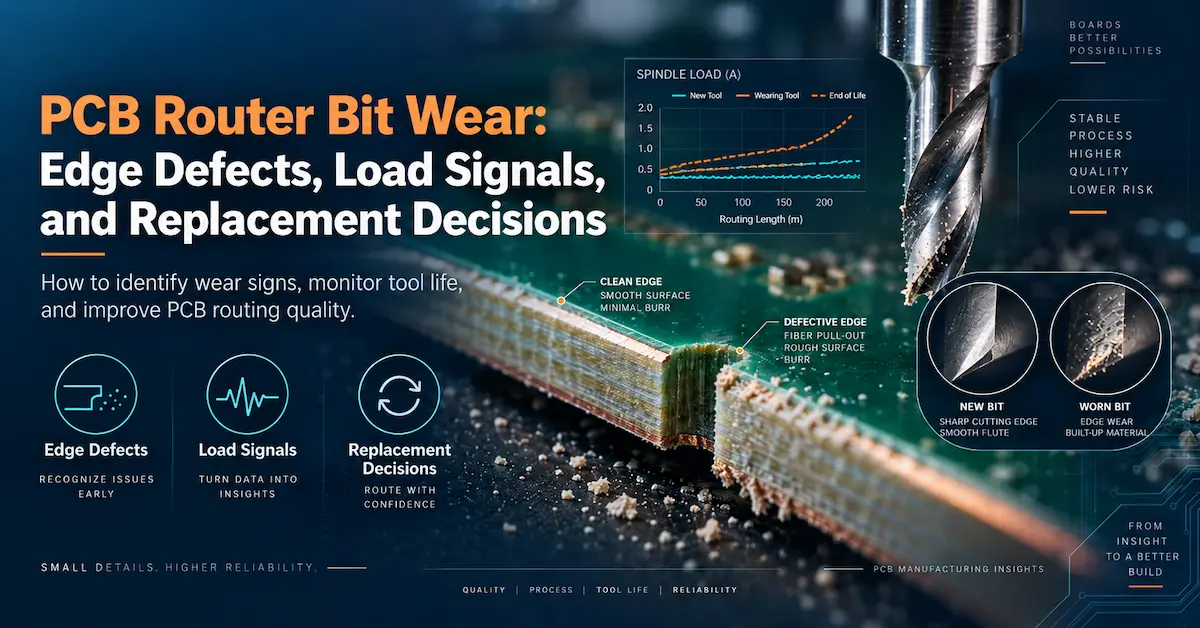
Tool replacement limits and ongoing wear diagnosis should be managed separately from initial tool selection. See the existing PCB router bit wear and replacement guide for that specific topic.
11. Standard Versus Custom PCB Router Bits: When Is a Special Design Necessary?
Standard cutters are often suitable when board material, geometry, and operating conditions fall within a supplier's validated product range.
A customized cutter may deserve evaluation when an application requires unusual cutting length, restricted slot access, specific edge characteristics, specialized flute geometry, or a combination of materials that standard cutters cannot process satisfactorily.
Before requesting custom PCB routing tools, define the manufacturing problem in measurable terms.
Ask the tooling manufacturer to confirm dimensional capability, material compatibility, sample availability, inspection documentation, minimum order requirements, and delivery schedule.
For CHIKIN machine projects, buyers can discuss spindle compatibility, tooling interfaces, process requirements, and appropriate machine configuration. Availability of specific cutter types or custom-made bits must be confirmed separately; the equipment range should not be interpreted as a guarantee that every cutter geometry is stocked.
12. PCB CNC Router Bits RFQ: What Should Industrial Buyers Send?
A technically complete request for quotation reduces the risk of receiving an attractive but unsuitable offer.
| RFQ Information | Details to Provide |
|---|---|
| PCB material | FR4, multilayer, aluminum-core, rigid-flex, or other construction |
| Material thickness | Nominal thickness, variation, and any routing stack |
| Board geometry | Routing drawing, minimum slot, contours, internal radii |
| Tool requirement | Preferred diameter, cutting length, geometry, shank |
| Machine information | Brand, model, spindle, holder or collet specification |
| Process conditions | Current speed, feed, routing depth, and extraction method |
| Quality requirement | Dimensional limits, visual acceptance, critical features |
| Production volume | Expected panels per shift and product mix |
| Existing problems | Breakage, burrs, vibration, rejected edges, or slow output |
| Commercial scope | Samples, tool quantities, documentation, delivery destination |
Need to confirm tool and machine compatibility for your PCB production line?
CHIKIN CNC, operated by Shenzhen ChiKin Automation Equipment Co., Ltd., develops PCB drilling and routing equipment for industrial board-processing applications.
Explore the CHIKIN PCB drilling and routing equipment range, or contact CHIKIN CNC with your board material, routing drawing, production target, and current cutter specification.
The objective is to identify a machine and tooling approach that can be validated against your real manufacturing requirements—not to recommend a cutter based only on catalog diameter.
13. Frequently Asked Questions About PCB CNC Router Bits
1. What are the best PCB CNC router bits for FR4?
Solid carbide router bits designed for abrasive glass-reinforced laminates are common candidates. Diamond-cut geometries are worth testing, but the best tool depends on board thickness, required edge finish, slot geometry, spindle condition, and approved cutting parameters.
2. Are diamond-cut router bits made from diamond?
Not necessarily. Diamond-cut typically describes a multi-edge cutting pattern. A diamond-coated tool or PCD cutter uses a different material technology. Buyers should confirm the actual substrate and coating rather than relying on the product name.
3. Can the same PCB router bit cut FR4 and aluminum PCBs?
Only when the cutter supplier confirms suitability and the process has been qualified. Glass-reinforced laminate and aluminum generate different cutting behavior, so one geometry should not be assumed optimal for both.
4. What router bit diameter is best for PCB slots?
The answer depends on nominal slot width, required tolerance, internal corner geometry, machine runout, and available cutter sizes. Select the cutter using the mechanical drawing and confirm the actual result through sample machining.
5. Should I use a single-flute or two-flute cutter for aluminum PCB routing?
Both geometries may be considered depending on the aluminum construction and machining conditions. Evaluate chip evacuation, cutting load, surface quality, rigidity, and the tool manufacturer's recommendations. Neither design is universally superior.
6. What is the difference between a PCB drill bit and a PCB end mill?
A drill primarily produces holes with axial cutting. An end mill or router bit is designed for material removal during lateral movement. Tool geometry and machine compatibility must match the intended operation.
7. Are 0.5 mm router bits suitable for industrial PCB routing?
They can be suitable for specific fine-feature applications when the machine, holder, cutting conditions, and board material support them. Small-diameter cutters require careful attention to runout, deflection, and breaking risk. Tool availability alone does not establish process capability.
8. Can router bits affect PCB delamination?
Yes. Inappropriate cutting forces, dull geometry, poor support, and unsuitable processing conditions can contribute to laminate damage. However, delamination can also involve material condition or other manufacturing factors. Diagnose the full process before blaming the cutter.
9. How should a PCB factory compare router bit suppliers?
Provide identical drawings, material information, quality requirements, and testing conditions. Compare dimensional consistency, sample results, identification and traceability, applicable specifications, qualified output, and commercial terms—not just unit price.
10. Can CHIKIN CNC help evaluate router bit compatibility?
CHIKIN CNC provides PCB drilling and routing equipment with different spindle and automation configurations. Buyers can submit their board drawings, tool details, and production requirements for a machine-compatibility discussion. Specific cutter availability, custom tooling supply, and processing performance should be confirmed for each project.
Conclusion
Choosing the right PCB CNC router bits requires a complete evaluation of the PCB material, cutting geometry, diameter, tool length, machine interface, and finished-board quality requirements.
For FR4, abrasion-resistant carbide geometry and controlled fiber cutting are important considerations. For aluminum-core PCBs, chip formation, burr control, and suitable non-ferrous cutting geometry require additional attention. Fine slots and multilayer constructions demand careful coordination between tooling, CNC motion, board support, and inspection.
The most reliable purchasing method is to qualify the complete process on representative boards before approving repeat orders. A successful choice is defined by stable, acceptable manufacturing output—not simply by cutting speed or the lowest cutter price.
For PCB manufacturers planning a new routing system or reviewing tooling compatibility on existing equipment, CHIKIN CNC offers drilling and routing machine configurations suited to different production requirements.
Contact CHIKIN CNC for a technical equipment review and provide your PCB material, routing files, cutter specifications, and target output. A clearly defined application is the strongest starting point for a reliable routing process and a more informed equipment investment.