



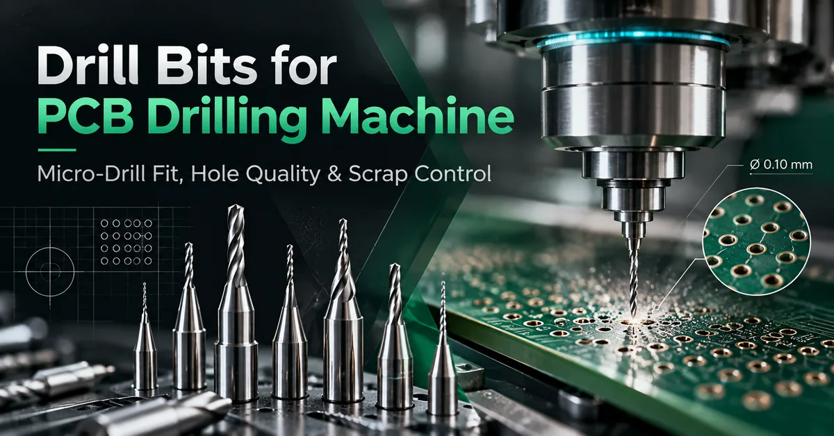
Choosing the right drill bits for PCB drilling machine production is essential for manufacturers processing high-density, multilayer, and precision printed circuit boards. An unsuitable micro-drill can contribute to hole-position variation, excessive burrs, resin smear, broken tools, and unnecessary production interruptions.
The correct PCB drill bit must match the required hole diameter, board construction, cutting conditions, and machine tool-holding system. A high-speed spindle alone cannot compensate for an unsuitable cutter or poorly controlled drilling process.
For B2B purchasing teams, tool selection should begin with finished-hole specifications and end with documented production qualification—not a comparison of drill prices alone.
This guide explains how to evaluate carbide micro-drills, confirm CNC compatibility, compare supplier specifications, and prepare a practical request for quotation (RFQ).
1. What Are Drill Bits for PCB Drilling Machines?
PCB drill bits are precision cutting tools designed to produce holes in printed circuit boards before subsequent manufacturing operations, such as desmearing and through-hole metallization.
Industrial PCB drilling often involves small-diameter tools operating in high-speed CNC spindles. The tools must cut through materials such as epoxy resin, glass reinforcement, copper, and other laminate constituents while maintaining acceptable hole position and wall quality.
Unlike conventional general-purpose drills, PCB micro-drills are selected for demanding conditions involving repeated holes, abrasive materials, and controlled dimensional requirements.
Typical applications include:
-
Plated through-hole preparation in multilayer PCBs.
-
Mechanical via drilling in suitable board constructions.
-
Component lead and connector holes.
-
Mounting and mechanical fastening holes.
-
Registration and tooling holes.
-
Precision holes in selected rigid and specialty laminates.
Solid tungsten carbide is commonly used for PCB drilling because its hardness and wear resistance are suitable for abrasive glass-reinforced materials.
However, not every hole should be drilled mechanically. Very small blind microvias and other high-density interconnect features may require laser drilling.
Which Buyers Need Specialized PCB Micro-Drills?
The primary buyers include PCB fabrication plants, HDI manufacturers, multilayer board producers, production engineers, equipment maintenance teams, and purchasing managers responsible for drilling consumables.
They need tools that deliver repeatable accepted output, reliable machine integration, and predictable procurement quality.
2. How to Select PCB Drill Bits for Different Board Materials
Material construction is one of the first variables to establish when selecting a drill.
Different substrates create different cutting loads, temperatures, wear patterns, and hole-wall defects.
FR4 PCB Drilling
FR4 contains glass-fiber reinforcement and epoxy resin.
Glass fibers are abrasive, while resin can be affected by drilling heat. An unsuitable drill or process can contribute to rough hole walls, glass-fiber damage, and resin smear.
Fine-grain solid carbide drills are common candidates for this application.
Engineers should evaluate drill geometry, point quality, flute design, and the supplier's recommended operating conditions.
Multilayer PCB Drilling
Multilayer boards introduce additional considerations involving copper layers, registration, drilling depth, and subsequent plating.
A drill must produce acceptable holes through the complete laminate construction—not merely penetrate the board.
Hole location, copper interaction, wall condition, and reliability of the finished plated-through hole are critical evaluation factors.
Specialty and High-Frequency Laminates
PTFE-based and ceramic-filled laminates may require different drilling strategies from standard FR4.
For example, AGC Multi Material's technical processing guidance for RF-35TC and RF-60TC discusses carbide point geometry, chip load, flute length, entry materials, and drill replacement frequency.
These recommendations apply to the specified materials and should not be treated as universal FR4 drilling parameters.
Material Compatibility Comparison
| PCB Material | Candidate Drill Type | Primary Concern | Qualification Priority |
|---|---|---|---|
| Standard FR4 | Solid carbide PCB drill | Abrasive wear and resin smear | Hole-wall condition |
| Multilayer FR4 | Precision carbide micro-drill | Registration and hole consistency | Position and cross-section |
| High-density rigid PCB | Small-diameter carbide drill | Deflection and breakage | Drill stability and minimum feature requirements |
| Ceramic-filled laminate | Application-qualified carbide or coated tool | Abrasive filler and tool life | Material-specific test |
| PTFE-based laminate | Laminate-compatible precision drill | Resin smear and heat | Supplier processing guidance |
| Aluminum-core PCB | Tool qualified for the entire metal/dielectric stack | Burrs, cutting load and material transition | Full-stack sample drilling |
Procurement takeaway: Do not approve a PCB drill bit solely because its diameter matches the drawing. Confirm suitability for the complete material construction.
3. PCB Drill Bit Diameter: Drilled Hole vs Finished Hole
One of the most important purchasing distinctions is the difference between drill diameter and finished-hole diameter.
For plated through-holes, the mechanical drilling diameter is not necessarily the same as the final hole diameter after metallization.
Copper plating and other process effects influence the finished opening.
Therefore, a supplier cannot determine the correct drill size from the final hole requirement alone without understanding the manufacturer's plating process and tolerance strategy.
For each hole family, communicate:
-
Required finished-hole diameter.
-
Plated or non-plated designation.
-
Hole diameter tolerance.
-
Board thickness and material.
-
Minimum annular ring or registration requirements.
-
Applicable customer drawing and inspection specification.
Does a Smaller Drill Always Improve PCB Precision?
No.
Smaller tools can produce smaller holes, but their stiffness and resistance to lateral loading generally decrease as diameter decreases.
Runout, tool projection, stack height, and cutting parameters become increasingly important.
Choose the smallest diameter that meets the design and validated manufacturing requirements—not the smallest tool offered by the catalog.
4. Essential Technical Specifications for PCB Drill Bit Procurement
A technically complete drill purchase specification should identify the cutter, its mounting interface, and its intended operating application.
PCB Micro-Drill Specification Table
| Specification | Procurement Requirement | Manufacturing Significance |
|---|---|---|
| Drill diameter | Nominal size and tolerance | Hole-size control |
| Shank diameter | Exact mounting dimension | Spindle-holder compatibility |
| Overall length | Total tool length | Machine and magazine clearance |
| Flute length | Effective cutting and chip-clearance length | Drilling-depth capability |
| Point geometry | Tool supplier's specified point configuration | Centering and cutting behavior |
| Helix geometry | Material-compatible flute design | Chip evacuation |
| Carbide grade | Defined material grade or supplier specification | Wear and breakage characteristics |
| Coating | Uncoated or validated coated option | Application-specific tool performance |
| Tool collar | Collar dimensions and positioning, if used | Automatic tool handling |
| Maximum operating speed | Manufacturer-approved conditions | Safe process operation |
| Tool identification | Part number and lot number | Production traceability |
| Inspection documentation | Dimensions and applicable test records | Incoming quality verification |
Why Is Shank Size Important?
A common industrial PCB drill shank diameter is 3.175 mm (1/8 inch), although other sizes exist.
A matching nominal shank diameter does not automatically confirm compatibility.
The machine's collet or holder, clamping method, tool length, collar position, and automatic tool changer must all support the selected tool.
Buyers should request the actual holder specification before ordering bulk drill quantities.
Why Does Flute Length Matter?
Flute length influences the drilling depth available for material penetration and chip evacuation.
An excessively short flute can create clearance problems. Excessively long, slender cutting geometry can increase deflection risk.
The appropriate length depends on the board stack, entry material, backup material, and qualified penetration depth.
5. Matching Drill Bits to CHIKIN PCB Drilling Machines
Machine-tool compatibility matters as much as the drill specification itself.
CHIKIN CNC, operated by Shenzhen ChiKin Automation Equipment Co., Ltd., develops precision PCB drilling and related automated equipment for industrial board manufacturing.
Its published drilling-machine range includes two- and four-spindle configurations.
CK-02D vs CK-04D Drilling Tool Compatibility
| Specification | CK-02D | CK-04D |
|---|---|---|
| Machine type | Dedicated PCB drilling | Dedicated PCB drilling |
| Number of spindles | 2 | 4 |
| Published spindle speed | 160,000–200,000 RPM | 160,000–200,000 RPM |
| Published tool diameter range | 0.15–6.35 mm | 0.15–6.35 mm |
| Spindle power | 0.85 kW per spindle | 0.85 kW per spindle |
| Tool management | Automatic tool changing | Automatic tool changing |
| Tool inspection | Length, diameter, broken-tool detection | Length, diameter, broken-tool detection |
| Main purchasing consideration | Balanced dual-spindle drilling capacity | Higher parallel drilling capacity |
Specifications are based on the published CHIKIN product descriptions. Final spindle, holder, magazine, and tooling compatibility must be confirmed for the ordered machine configuration.
The CK-02D 2 Spindle PCB Drilling Machine is worth evaluating for factories requiring automated dual-spindle drilling.
The CK-04D 4 Spindle PCB Drilling Machine provides a four-spindle configuration for facilities seeking additional production capacity.
Both product descriptions include high-speed spindle systems, granite machine structures, and automatic tool-management features.
Important: A published 200,000 RPM spindle capability does not mean every drill diameter should operate at that speed.
The manufacturer's cutting recommendations, tool-holder limitations, drilling material, and actual process requirements determine the appropriate settings.
Likewise, the equipment's published positioning accuracy must not be represented as a guaranteed finished-hole tolerance.
6. How Do Entry Materials, Backup Boards, and Stack Height Affect Drilling?
Even high-quality carbide drill bits may produce poor holes when the board stack is incorrectly prepared.
A complete drilling setup includes the PCB material, entry sheet, backup board, fixation arrangement, spindle, and extraction system.
Entry Material
Entry sheets help protect the board surface and support drill entry.
Depending on the process, suitable materials can also reduce entry burrs and improve the initial engagement of the drill point.
Selection should consider material compatibility, drill diameter, and the intended stack arrangement.
Backup Material
Backup boards support the workpiece during drill exit.
An unsuitable or damaged backup can contribute to exit burrs, contamination, and inconsistent hole quality.
Stack Height
Drilling multiple panels can improve output per drilling cycle, but greater stack thickness also increases the effective cutting engagement.
A thin micro-drill must remain sufficiently rigid while evacuating chips throughout the depth.
There is no universally acceptable number of panels per stack. The limit depends on material construction, drill diameter, flute geometry, and quality requirements.
For a more detailed process comparison, see CHIKIN's PCB drilling stack height guide.
7. Spindle Speed, Feed Rate, and Micro-Drill Performance
Correct cutting parameters are essential for maintaining micro-drill reliability.
For drilling, feed per revolution is a useful process variable.
Feed Rate (mm/min) = Spindle Speed (RPM) × Feed per Revolution (mm/rev)
This relationship describes programmed axial feed, but does not establish a safe cutting condition by itself.
A suitable process must also consider drill diameter, material, point geometry, drill penetration, chip evacuation, and the manufacturer's recommended limits.
An excessive feed may increase loading and breakage risk. Inappropriate speed and feed combinations can create heat-related hole defects or inefficient cutting.
For production qualification:
-
Start with the tool and laminate manufacturers' process recommendations.
-
Verify actual spindle and holder compatibility.
-
Establish a controlled sample drilling program.
-
Inspect hole diameter, location, burrs, and wall condition.
-
Repeat the test over representative drill usage.
-
Record approved settings by tool and material combination.
Avoid changing speed, feed, stack height, and tool supplier simultaneously during troubleshooting.
8. Common PCB Drilling Defects and How to Investigate Them
A drilling defect does not automatically mean the bit is defective.
Machine condition, fixtures, material variation, entry and backup boards, and programmed settings can create similar symptoms.
| Defect | Possible Contributing Factors | First Investigation |
|---|---|---|
| Broken micro-drill | Excessive loading, runout, poor support, unsuitable geometry | Tool, holder, cutting parameters |
| Oversized holes | Tool runout, wrong diameter, measurement variation | Tool identification and metrology |
| Hole position variation | Board movement, registration, drill deflection | Fixture, alignment, positioning |
| Entry burrs | Entry material, cutting engagement, drill condition | Entry-sheet and tool inspection |
| Exit burrs | Inadequate backup support, tool wear | Backup and penetration depth |
| Resin smear | Heat, material characteristics, cutting process | Hole-wall evaluation and parameter review |
| Rough hole walls | Tool condition, material, chip evacuation | Cross-section and process inspection |
| Inconsistent results across spindles | Different holders, runout, calibration, tool lots | Head-by-head controlled comparison |
When hole-position variation is the main concern, CHIKIN's PCB hole position accuracy guide provides a separate diagnostic framework.
For tool-holding problems, the PCB spindle collet cleaning guide explains how to investigate contamination, seating, and runout without assuming that replacing a drill will solve the problem.
9. Quality Control: How Should PCB Factories Qualify a New Drill Bit?
Industrial buyers should approve micro-drills using representative production results.
A supplier's dimensional certificate is useful, but it cannot independently prove that the cutter will meet every finished-board requirement.
Recommended Qualification Procedure
Step 1 — Incoming Inspection
Confirm part numbers, diameter, shank size, overall length, flute geometry, condition, and lot identification.
Step 2 — Machine Compatibility
Verify the approved holder, installation depth, tool changer, and relevant clearance.
Step 3 — Sample Drilling
Use actual production material and a controlled drilling program. Include representative hole sizes and board locations.
Step 4 — Finished-Hole Inspection
Measure hole geometry and position. Inspect burrs, smear, wall condition, and other critical defects.
Step 5 — Tool-Life Assessment
Monitor hole quality at different stages of drill usage. Establish an application-specific replacement criterion.
Step 6 — Production Approval
Record accepted tool specifications, machine configuration, cutting conditions, inspection results, and supplier-lot requirements.
For finished printed-board acceptance, relevant customer requirements and applicable editions of IPC-A-600 and IPC-6012 can provide a recognized quality framework.
These standards do not constitute certification of an individual drill-bit brand.
The final acceptance criteria must match the customer's board drawing and agreed manufacturing requirements.
10. Why Tool Cost per Accepted Hole Matters More Than Unit Price
Price comparison is an important purchasing task, but the lowest-priced cutter may not deliver the lowest manufacturing cost.
A more meaningful metric is:
Drill Tooling Cost per Accepted Hole = Total Drill Tooling Expenditure ÷ Number of Accepted Holes
The calculation should use actual qualification data rather than estimated tool life.
Additional costs include machine stoppages, tool changes, inspection, rejected panels, and damage associated with broken drills.
Production managers should also measure accepted holes per machine-hour rather than assuming spindle count translates directly into proportional output.
Commercial Comparison Checklist
| Evaluation Factor | Why Buyers Should Compare It |
|---|---|
| Unit drill price | Initial consumable expenditure |
| Qualified hit count | Usable tool life under defined conditions |
| Accepted-hole output | Actual manufacturing value |
| Drill breakage frequency | Unplanned interruption risk |
| Hole quality consistency | Rejection and rework exposure |
| Tool-change time | Production availability |
| Batch consistency | Requalification and incoming inspection burden |
| Supplier delivery reliability | Consumable inventory risk |
A four-spindle machine can provide additional capacity, but the actual increase depends on board layout, tool changes, machine utilization, and the approved production process.
Similarly, longer tool life is valuable only when hole quality remains acceptable.
11. Standard vs Custom PCB Drill Bits: What Should Buyers Request?
Standard carbide micro-drills are often appropriate when the required diameter, cutting length, geometry, and holder interface match an established tooling specification.
Specialized drill designs may need consideration for unusual board thicknesses, demanding laminate constructions, restricted access, or processes in which standard tools cannot meet quality requirements.
A custom tooling inquiry should include the engineering problem and its acceptance criteria, not simply a request for a stronger or longer-lasting drill.
Ask the tooling supplier to clarify:
-
Available diameter and tolerance options.
-
Carbide substrate and cutting geometry.
-
Compatible materials and process limitations.
-
Inspection and lot-traceability documentation.
-
Sample quantities and qualification support.
-
Minimum order quantity and confirmed lead time.
-
Regrinding or reuse options, where applicable.
CHIKIN's verified core business is PCB drilling and routing equipment. Specific drill-bit stock, custom cutter manufacturing, and tooling supply arrangements should be confirmed directly rather than assumed.
For equipment integration projects, the priority is to ensure that the proposed drill and machine configuration can be qualified together.
12. PCB Drill Bit RFQ Checklist for B2B Procurement
A clear RFQ helps suppliers understand the application and reduces the risk of receiving tools that fit the nominal diameter but fail in production.
| Information Required | What the Buyer Should Provide |
|---|---|
| PCB material | FR4, multilayer, PTFE-based, metal-core or other |
| Board construction | Thickness, layers, copper and material stack |
| Hole specification | Drill size, finished size, tolerance, plated/non-plated |
| Tool interface | Shank size, holder type, tool collar requirements |
| Machine model | CNC manufacturer, spindle configuration, speed limits |
| Process information | Entry material, backup, stack height, current parameters |
| Quality requirements | Hole geometry, registration, wall and burr acceptance |
| Production demand | Required drilling output, tool consumption, shift pattern |
| Existing issues | Drill breakage, smear, position variation, downtime |
| Commercial requirements | Samples, quantity, documentation, delivery and support |
Request a CHIKIN CNC Machine and Tooling Compatibility Review
If your factory is evaluating new drilling equipment, start with the actual PCB and tool requirements.
CHIKIN CNC offers dedicated multi-spindle PCB drilling machines and related precision equipment for industrial production.
For a practical equipment discussion, provide your board material, panel size, hole-size distribution, production target, and intended drill specifications.
The engineering team can review the proposed machine configuration and discuss which tooling interfaces and operating capabilities need confirmation before purchase.
Contact CHIKIN CNC for a drilling-machine quotation and include your PCB drawings and current manufacturing challenges.
13. Frequently Asked Questions About Drill Bits for PCB Drilling Machine Production
1. What material is best for PCB drilling machine drill bits?
Solid tungsten carbide is commonly selected for industrial PCB drilling because it offers hardness and wear resistance suitable for abrasive glass-reinforced laminates. The exact carbide grade and geometry should be qualified for the intended application.
2. What drill bit sizes are used in PCB manufacturing?
PCB drilling uses different diameters for vias, component holes, tooling holes, and mechanical features. CHIKIN's CK-02D and CK-04D list a 0.15–6.35 mm drilling-tool diameter range, but the usable size and cutting conditions must be verified for each application.
3. Are 3.175 mm shank PCB drill bits universal?
No. Although 3.175 mm is a common shank size, holder geometry, gripping requirements, tool length, collars, and automatic tool-change compatibility vary. Always confirm the installed spindle and holder specification.
4. Can a PCB drilling machine use the same drill bits for FR4 and PTFE?
Only when the tool supplier approves the relevant materials and sample qualification confirms acceptable results. PTFE-based and ceramic-filled laminates may require different cutting parameters and tool-management rules from standard FR4.
5. How many holes can one carbide PCB drill bit produce?
There is no universal hit-count guarantee. Tool life depends on diameter, material, stack height, speed, feed, required hole quality, and other process factors. Establish the permitted hit count through controlled qualification.
6. What causes small PCB drill bits to break?
Possible causes include excessive cutting load, poor chip evacuation, unsuitable tool geometry, high runout, incorrect clamping, board movement, or excessive stack engagement. A structured investigation is necessary before identifying the root cause.
7. Does a 200,000 RPM spindle require special PCB drills?
The tool must be compatible with the spindle system and approved operating conditions. A high-speed machine rating does not automatically authorize every cutter to operate at maximum speed.
8. What is the difference between PCB micro-drilling and laser microvia drilling?
Mechanical micro-drilling uses a rotating cutting tool to remove material and is suitable for many through-hole applications. Laser drilling uses focused energy and is commonly employed for very small, often blind, HDI microvias. The appropriate method depends on the design and process.
9. How should purchasing managers verify PCB drill bit quality?
Request a complete specification, supplier identification, applicable inspection data, sample tools, and lot traceability. Qualify the drills on representative production boards and evaluate accepted-hole output rather than catalog claims alone.
10. How can CHIKIN CNC help when selecting drilling equipment for new micro-drills?
CHIKIN CNC provides dedicated PCB drilling equipment, including CK-02D and CK-04D multi-spindle models. Buyers can discuss drill-diameter requirements, spindle configuration, automatic tool handling, and application-specific equipment compatibility before finalizing a machine purchase.
Conclusion
Selecting reliable drill bits for PCB drilling machine operations requires more than comparing diameter, carbide material, or unit price.
The most important factors are compatibility with the PCB construction, correct tool dimensions, reliable spindle holding, suitable drilling conditions, and verified finished-hole quality.
For multilayer and high-density production, drill-bit procurement should be integrated with machine qualification, process control, and documented inspection. A small reduction in tooling price has little value if it increases broken drills, defective holes, or production interruptions.
By establishing clear RFQ requirements and evaluating drill performance under real production conditions, PCB manufacturers can make more informed purchasing decisions and improve control over drilling-related operating costs.
For factories considering automated precision drilling equipment, CHIKIN CNC offers dedicated two- and four-spindle machine configurations designed for different manufacturing demands.
Explore CHIKIN's PCB drilling equipment or request a technical consultation and quotation with your PCB material, hole specifications, and production requirements. The right combination of machine capability, qualified tooling, and controlled process conditions is the foundation of dependable PCB drilling.