



What Is PCB Drilling Stack Height?
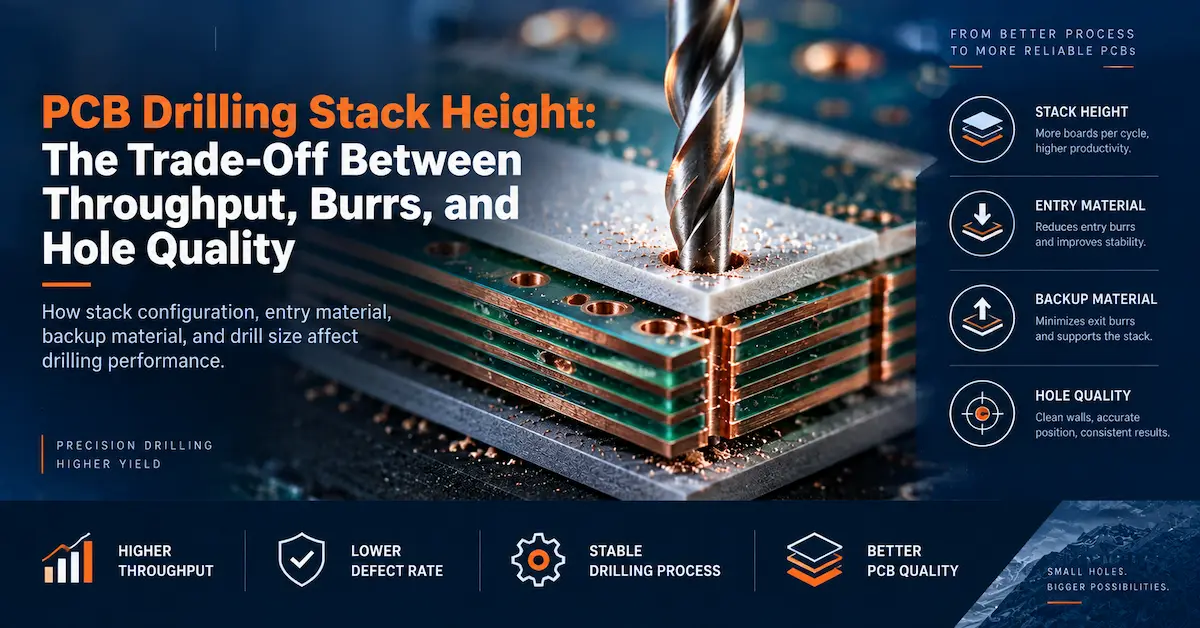
PCB drilling stack height is the combined thickness of the PCB panels drilled together during one machining cycle. It should be distinguished from the complete drilling sandwich, which may also include a PCB drill entry material above the panels and backup material underneath them.
For a production manager, increasing the number of panels in a PCB drilling stack looks attractive because one programmed drilling movement can produce holes in several panels instead of one. However, the drill must travel farther through material, chips have a longer path to escape, the cutting edge remains engaged for longer, and the lower boards are farther from the point where the drill first enters.
That is why stack height should not be selected from throughput alone. It is a process variable that must be qualified together with drill diameter, flute geometry, panel thickness, laminate construction, spindle and feed settings, entry and backing materials, extraction, and the required hole-quality acceptance criteria.
Buyers evaluating a new drilling platform should therefore include actual panel thickness, typical stack arrangement, hole sizes, and production volume in the equipment RFQ rather than asking only for maximum machine speed. CHIKIN’s PCB Drilling Machine RFQ & Factory Acceptance Guide provides a useful framework for communicating those production requirements before equipment selection.
Why Higher Stack Height Can Increase Throughput
The production logic is straightforward. If the same drilling program processes more acceptable panels during each machine cycle, output per drilling operation can increase. This can reduce repeated loading, positioning, and non-cutting movements per finished panel.
But panel count alone is not throughput.
A four-panel stack that produces excessive burrs, premature drill wear, rough walls, or registration problems can create more inspection, sorting, rework, and scrap than a three-panel stack that runs consistently.The useful production metric is therefore accepted panels per unit of production time, not simply panels loaded per stack.
An illustrative comparison makes this clearer. Suppose a two-panel stack produces 100 acceptable stacks during a shift: that represents 200 accepted panels. If a three-panel arrangement reduces cycle count and produces 80 acceptable stacks, output becomes 240 accepted panels. But if quality losses reduce the accepted result to only 65 stacks, the same nominal three-panel setup yields 195 accepted panels. The higher stack no longer delivers a production advantage.
These numbers are examples only, not CHIKIN machine-performance data. The purpose is to show why stack height must be evaluated using actual accepted output.
Stack Height vs Hole Quality: Why More Panels Change the Cutting Process
The relationship between stack height vs hole quality becomes more critical as drill diameter decreases, total penetration increases, or laminate construction becomes harder to drill consistently.
When the drill enters the upper panel, chips can move toward the flute opening over a relatively short distance. As penetration becomes deeper, chips generated near the lower portion of the stack must travel farther before leaving the cutting area.If the flute space, extraction, drill geometry, or process conditions are not suitable for this additional load, chips may accumulate rather than evacuate cleanly.
At the same time, the drill is exposed to lateral cutting forces through a longer path. A small drill does not behave like an infinitely rigid pin. Runout, tool geometry, board construction, entry conditions, and accumulated wear can all influence its path through a deeper stack.
The consequence is that one stack-height change can affect several quality characteristics at the same time.
| Quality characteristic | Why stack height can matter | What to verify |
|---|---|---|
| Entry burr | Drill entry, entry-sheet support and tool condition affect the top surface | Compare top-surface burrs under the same tool condition |
| Exit burr | Lower-panel support and backup condition become important at breakthrough | Inspect the bottom panel and backing setup |
| Hole-wall condition | Heat, chips,glass/resin cutting and tool wear affect wall texture | Use a defined microsection method |
| Smear risk | Increased heat and rubbing may contribute under unsuitable conditions | Inspect inner-layer interfaces separately |
| Hole position | Longer penetration may increase sensitivity to tool deflection | Measure upper and lower panel positions independently |
| Hole diameter | Tool wear,runout and cutting behavior may change results through the stack | Measure representative positions and stack levels |
| Tool life | Greater material engagement per cycle increases total cutting work | Track hits and quality together |
The correct stack is therefore not the one with the largest number of boards. It is the highest stack that can repeatedly meet the required drilling specification within an economically sensible tool-life and process window.
Drill Diameter Is One of the First Limits to Review
Small-diameter drills are generally more sensitive to deflection, wear, runout, and chip-loading conditions than larger tools. This means a stack arrangement that works acceptably for larger mechanical holes may not be suitable for the smallest via holes on the same product.
A factory should therefore avoid defining one universal stack height for every hole size simply because it simplifies production planning.
Instead, group drilling programs by meaningful tool and product requirements.Compare drill diameter, panel thickness, laminate, copper construction, required registration, and qualified tool life. If the smallest drill determines the stack limit, document that limit rather than allowing operators to increase panel count because larger tools appear stable.
CHIKIN’s 2 Spindle PCB Drilling Machine and 4 Spindle PCB Drilling Machine are published as multi-spindle drilling configurations for production environments. Equipment capacity, however, does not replace process qualification: the stack, tool, board construction, and acceptance method still need to be validated for the actual job.
PCB Drill Entry Material: Why the Top Layer Matters
The PCB drill entry material sits above the PCB stack and provides the first controlled surface encountered by the drill.
Its function is not simply to protect the board. Depending on the selected material and process, an entry sheet can help stabilize drill entry, reduce surface damage, support cleaner entry conditions, and contribute to heat management.It can also influence how consistently the drill begins its path before entering the laminate.
Poor entry conditions can make a stack-height problem appear to be a machine problem. If the entry material varies in thickness, flatness, hardness, or condition, the first stage of drilling is no longer consistent.
For troubleshooting, record the entry-material type and lot together with stack height and tooling information. When running an experiment, do not change entry material and stack height simultaneously unless the objective is specifically to qualify a new combined process. Otherwise, it becomes difficult to determine which variable caused the result.
Entry sheets should also be evaluated across their useful working condition rather than only when freshly installed. A production process is only repeatable if the actual condition used on the line remains within the qualified range.
Backup Material Controls What Happens at Drill Exit
The backup material—also called backing or backer material—supports the bottom of the drilling stack and receives the drill after it exits the final PCB.
This makes it particularly relevant to bottom-surface burrs and breakthrough conditions.The backing should provide adequate support without introducing an unsuitable combination of contamination, debris, hardness, or excessive drill penetration.
The drill should penetrate far enough to complete the hole through the bottom panel. Excessive penetration does not automatically improve quality. It increases unnecessary tool travel and can generate additional debris or wear. Insufficient penetration, meanwhile, can leave incomplete breakthrough or poor exit conditions.
For a controlled evaluation, document backing type, thickness, flatness, penetration depth, replacement criteria, and the condition of the machine support surface. If bottom-panel burrs increase while upper panels remain stable, the backing arrangement deserves investigation before changing every drilling parameter.
Chip Evacuation Becomes More Difficult as the PCB Drilling Stack Gets Deeper
Chip evacuation is one of the central reasons that a larger PCB drilling stack cannot be evaluated by panel count alone.
Every additional thickness of laminate creates more cut material. The flute must transport that material away from the cutting zone while the tool continues rotating and advancing. When evacuation becomes insufficient, the cutting environment can change rapidly.
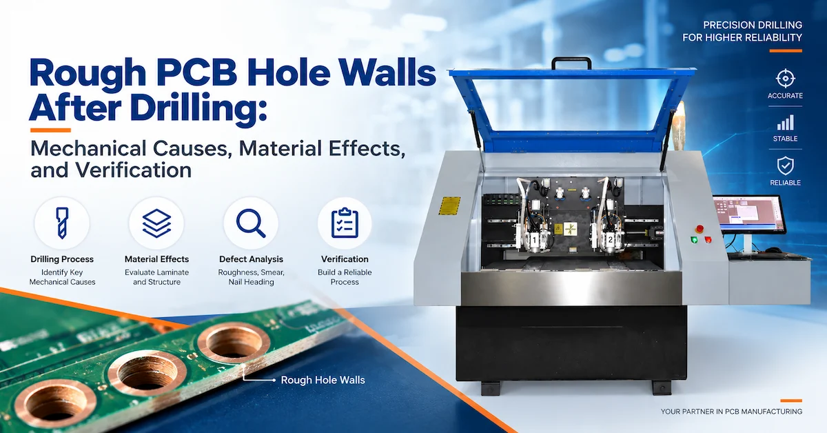
Signs that should trigger investigation include packed material in drill flutes, unusual debris around drilled areas, rising tool breakage, quality differences between upper and lower boards, deteriorating hole walls, or a stack-specific increase in process instability.
Extraction should therefore be checked as part of the complete drilling setup. Pressure-foot condition, vacuum flow, contact with the stack, local leakage, and debris collection can influence the effectiveness of chip removal.
A buyer comparing equipment should ask how the proposed machine handles extraction under the intended panel and stack conditions rather than treating dust collection as a secondary accessory. CHIKIN’s PCB Drilling Machine Buying Guide positions machine structure, spindle configuration, tooling support, board requirements, and production workflow as related selection factors rather than isolated specification numbers.
Feed Rate and Spindle Speed Must Be Evaluated With Stack Height
Changing stack height without reviewing cutting conditions can move a previously stable process outside its qualified window.
Feed rate determines how quickly the drill advances.Spindle speed determines the number of rotations during that movement. Their relationship affects the material removed during each revolution, while stack height determines how long those cutting conditions continue through the panel sandwich.
This is why “increase spindle speed for a deeper stack” or “reduce feed to improve quality” should not be treated as universal rules.
Reducing feed without understanding the resulting cutting condition can increase rubbing and heat. Increasing feed too far can raise cutting load and challenge chip evacuation. Increasing spindle speed can change heat and wear behavior without necessarily solving an underlying backing, entry, runout, or extraction problem.
The correct approach is to use a qualified starting window for the material and tool, change one controlled factor where practical, and inspect the resulting boards.
Material Construction Can Change the Acceptable Stack Height
Two panels with the same nominal thickness do not necessarily behave identically in drilling.
Glass style, resin system, copper distribution, layer count, laminate grade, panel flatness, and previous thermal processing can affect drilling behavior. A stack qualified for one multilayer construction should therefore not automatically be copied to another product simply because both are described as FR-4.
This is particularly important when the factory changes laminate suppliers, introduces a new multilayer construction, or moves between standard rigid boards and more demanding material systems.
Record the exact construction used during qualification. If quality changes after a material transition, compare material lot and construction before assuming that the drilling machine has lost accuracy.
For mixed-production factories, this usually leads to several qualified stack groups rather than one “maximum stack” rule.
How Stack Height Influences Burr Formation
Entry and exit burrs should be inspected separately because their causes and corrective actions are not necessarily the same.
Top-surface burrs can be influenced by drill entry, entry-sheet condition, cutting-edge condition, and local support. Bottom-surface burrs place greater emphasis on breakthrough conditions, backing support, tool condition, and penetration.
A taller stack adds another variable: boards occupy different vertical positions during the same drilling operation.
That makes it useful to label samples by stack position during qualification. Instead of inspecting a random panel and recording “burr acceptable,” retain the top, middle, and bottom panel identities.
If only the lowest board deteriorates, the process problem is different from a condition that appears equally on all panels. If quality gradually changes from top to bottom, stack-related cutting or evacuation behavior becomes more plausible.
Stack Height Can Also Affect Hole Position
Hole quality is not only surface finish.
A deeper drilling path can make small-diameter tooling more sensitive to runout, tool deflection, stack movement, and panel support. For products with limited annular-ring margin, the drilling team should therefore measure hole location as well as burrs and wall condition.
This is particularly important when a higher stack appears visually acceptable but lower panels show a different positional distribution.
Measure stack positions separately. If only a combined average is reported, a stable upper panel can hide deterioration in the bottom panel.
The same principle applies when comparing different drilling heads. A production qualification should determine whether the process remains acceptable across the relevant spindles and panel positions, not only whether one favorable sample passes.
Do Not Use Maximum Machine Capacity as the Production Stack Limit
A machine's physical Z travel, work area, spindle capability, or available clamping space may allow a certain panel arrangement mechanically. That does not make it a qualified production stack.
The usable PCB drilling stack height is ultimately a process result.
A valid production limit should satisfy the board's hole-size, position, burr, wall-quality, and downstream requirements while maintaining acceptable tool life and output. This limit may be below the physical capacity of the equipment.
Procurement teams should make this distinction during factory acceptance testing. A machine demonstration should use representative board material, hole sizes, panel thickness, and realistic stack arrangements. CHIKIN’s PCB Drilling Machine RFQ & Acceptance Guide recommends defining sample-processing expectations and acceptance criteria before equipment approval rather than relying only on machine videos or catalog descriptions.
How to Qualify PCB Drilling Stack Height
Stack-height qualification should preserve enough information to reproduce both a good and a bad result.
A practical qualification matrix can look like this:
| Variable | Record during trial | Why it matters |
|---|---|---|
| PCB construction | Material, thickness, layers, copper construction | Establishes the product being qualified |
| Stack configuration | Number of panels and total board-stack thickness | Defines the variable under study |
| Entry material | Type,thickness and condition | Influences drill entry |
| Backup material | Type, thickness and condition | Influences exit support |
| Tool | Diameter, specification, condition and hit count | Controls cutting behavior |
| Machine/head | Machine ID and spindle position | Identifies equipment-dependent variation |
| Cutting settings | Speed, feed,penetration and relevant program settings | Makes the result reproducible |
| Extraction | Pressure-foot and vacuum condition | Affects chip evacuation |
| Inspection | Burrs, position, diameter, wall condition and relevant defects | Determines whether quality remains acceptable |
| Stack position | Top, middle and bottom board identification | Shows depth-related deterioration |
Begin with a known stable condition. Increase stack height only as a controlled trial rather than changing tooling, feed, backing, entry sheet, and stack simultaneously.
Once a candidate setting has passed initial inspection, repeat the trial over representative tool usage and production conditions. A stack that works only with a brand-new drill is not necessarily a stable production process.
How to Compare Two-, Four-, and Other Multi-Spindle Machines
Stack height and spindle count solve different production problems.
Increasing stack height attempts to produce more boards under each drilling operation. Increasing spindle count provides additional simultaneous drilling capacity. Combining both without quality verification can maximize nominal output while also magnifying process risk.
A manufacturer facing capacity pressure should therefore compare several ways to gain output rather than automatically increasing stack thickness.
| Production approach | Potential value | Main question to verify |
|---|---|---|
| Higher stack on existing machine | More boards per drilling cycle | Does the lower stack position remain within specification? |
| Additional spindle capacity | More simultaneous drilling capability | Does each head maintain the required process result? |
| Better loading/automation | Reduces non-cutting time | Is loading currently the real production bottleneck? |
| Tool/process optimization | May improve usable tool life or cycle stability | Is the current process technically constrained or simply unoptimized? |
CHIKIN offers 2-spindle PCB drilling equipment and 4-spindle PCB drilling equipment for different production requirements. Buyers should compare those configurations using their actual hole patterns, board sizes, stack conditions, shifts, and acceptance criteria rather than extrapolating output solely from spindle count.
Cost: Measure Accepted Panels per Tool and per Shift
The commercial question behind stack height vs hole quality is not whether a taller stack is technically possible.It is whether the resulting process reduces the cost of acceptable production.
A useful comparison includes drilling time, tool consumption, entry and backup material, operator intervention, microsection and inspection requirements, scrap, rework, machine downtime, and accepted output.
Suppose a higher stack raises nominal panel output by 20% but shortens usable drill life and causes enough inspection rejects that accepted production increases by only 4%. Whether that change is worthwhile depends on the added tool, quality, and operating cost.
Again, the percentage here is illustrative, not CHIKIN production data.
The most useful KPI is often closer to cost per accepted panel than “maximum boards per stack.” That metric forces throughput and quality into the same purchasing discussion.
When a Lower Stack Is the Better Process
A lower stack may be preferable when drilling very small holes, demanding multilayer constructions, products with limited registration margin, materials not yet qualified, prototype or high-mix orders, or boards where microsection evidence shows lower-panel deterioration.
That is not a sign that the equipment is underperforming.
Process optimization is about controlling variation. A two-panel stack that produces stable accepted product can be commercially better than a four-panel arrangement requiring frequent sorting and troubleshooting.
Similarly, not every factory should pursue the same maximum stack. A high-volume producer may justify extensive qualification work because a small cycle improvement is repeated across large quantities. A prototype shop may value fast setup and low risk more than maximum panels per drilling cycle.
What Information Should You Send When Selecting a PCB Drilling Machine?
If stack height is important to your production target, do not submit only the phrase “we drill three boards at once.”
Provide the panel thickness, number of panels per intended stack, material construction, smallest and typical drill sizes, hole count, entry material, backing arrangement, target output, current tool life, and known quality problems. Include examples of burrs, rough walls, hole-position variation, or breakage when those issues already exist.
Also state whether the expected capacity increase must come from stack height, spindle quantity, automation, or a combination of them.
This gives the equipment supplier enough context to review the process rather than recommending a machine based solely on output claims. Buyers planning new equipment can use CHIKIN’s PCB drilling machine product range as a starting point and then submit application-specific requirements for technical evaluation.
FAQs About PCB Drilling Stack Height
1. What is PCB drilling stack height?
PCB drilling stack height normally refers to the combined thickness of PCB panels drilled together. The entry sheet and backing should be documented separately because they also affect the total drilling sandwich and process conditions.
2. Does increasing PCB drilling stack height always improve productivity?
No. A taller stack can increase nominal panels processed per cycle, but the real result depends on cycle time, tool life, burrs, wall quality, positional accuracy, inspection losses, and rejected panels.
3.How many PCB panels should be drilled in one stack?
There is no universal number suitable for every PCB. The stack should be qualified for the laminate construction, panel thickness, drill diameter, tooling, machine, process settings, and quality requirements.
4. Why does a taller PCB drilling stack create more burr risk?
Deeper drilling changes tool engagement, chip evacuation, breakthrough conditions, and tool wear. Bottom-panel support and backing conditions also become particularly important as the drill exits the stack.
5. What does PCB drill entry material do?
PCB drill entry material provides a controlled entry surface above the panel stack. Depending on its specification and application, it can assist drill entry, top-surface support, burr control, and process consistency.
6. Why is backup material important in PCB drilling?
Backup material supports the lower board during drill breakthrough, protects the machine support surface, and influences bottom-surface exit conditions.Its specification and replacement condition should be controlled.
7. Should the same stack height be used for every drill diameter?
Not necessarily. Small-diameter tools can be more sensitive to deflection, runout, chip evacuation, and wear, so the most demanding drill in the job may require a different qualified stack.
8. Can spindle speed compensate for an excessively high stack?
Not automatically. Speed, feed, drill geometry, laminate, extraction, tool condition, and stack height interact. Changing one parameter without verification may create a new quality problem instead of correcting the original one.
9. How should stack height vs hole quality be verified?
Inspect top, middle, and bottom boards separately using agreed criteria for burrs, hole diameter, hole position, wall condition, smear where relevant, and other product-specific requirements. Record tooling and drilling conditions with the inspection results.
10.What should I provide CHIKIN for a drilling-stack evaluation?
Provide PCB material and thickness, intended panel count, minimum and typical drill diameters, entry and backing materials, hole count, production target, tool-life information, current drilling parameters, and examples of any quality issues. This allows the equipment discussion to focus on the actual production process rather than an isolated machine specification.
Conclusion
The optimum PCB drilling stack height is not the tallest stack the machine can physically accept. It is the highest qualified stack that consistently produces acceptable holes at a sustainable production cost.
A useful PCB drilling stack study should evaluate throughput together with burr formation, chip evacuation, tool condition, hole position, wall quality, PCB drill entry material, and backup material. The comparison of stack height vs hole quality should also separate top, middle, and bottom panels so deterioration is not hidden inside an average result.
For manufacturers increasing PCB drilling capacity, stack height is only one option. Spindle configuration, machine stability, tool management, extraction, loading efficiency, and process control can be equally important. Review CHIKIN’s PCB drilling machines or contact CHIKIN CNC with your board construction, stack arrangement, drill sizes, quality requirements, and target output to evaluate an equipment and verification approach around your actual production conditions.