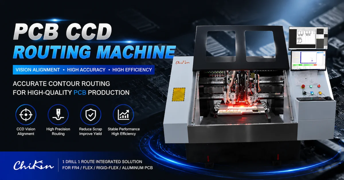




A CCD Routing Machine is designed for PCB manufacturers that require higher routing accuracy, better panel alignment, and more stable contour processing.
In PCB manufacturing, routing accuracy directly affects the final board dimensions, slot positions, edge quality, and assembly compatibility. Even a small positioning error can cause problems during enclosure fitting, connector installation, or downstream assembly.
Traditional PCB routing relies heavily on mechanical positioning and manual alignment. This may work for simple boards, but it becomes challenging when manufacturers process:
- High-density PCB designs
- Multilayer boards
- Small-batch orders
- Different PCB sizes
- Rigid-flex boards
- Precision contour shapes
A CCD routing system solves this problem by using a camera-based vision system to identify reference points before routing. The machine can detect the actual PCB position and adjust the routing path automatically.
For PCB factories, this means:
- Better contour accuracy
- Reduced setup errors
- Lower scrap rate
- More stable batch production
- Faster changeover between board models
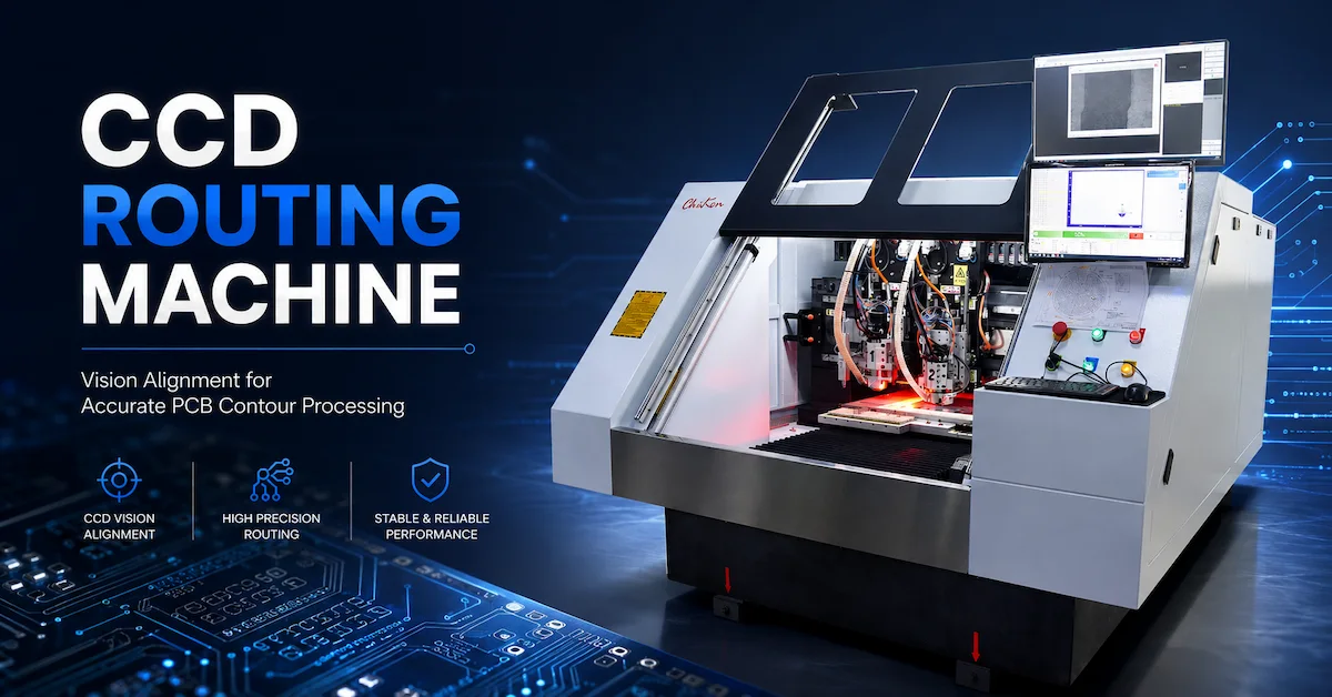
What Is a CCD Routing Machine?
A CCD Routing Machine is a CNC PCB routing system equipped with a CCD camera vision alignment function.
The CCD camera detects fiducial marks or reference points on the PCB panel. The control system then compares the actual board position with the programmed routing path and compensates for:
- Position deviation
- Rotation error
- Panel placement difference
- Alignment variation
Unlike standard routing equipment, a CCD routing machine does not assume that every PCB panel is perfectly positioned.
Instead, it measures the actual board condition before processing.
Typical applications include:
- PCB contour routing
- PCB outline cutting
- Slot processing
- Panel separation
- Precision board shaping
- Drill and route integrated processing
- Prototype PCB manufacturing
- Mid-volume PCB production
Why CCD Vision Matters for PCB Routing
1. Improves Routing Position Accuracy
PCB routing paths must match the actual board layout. If the panel shifts slightly during loading, the router may cut in the wrong position.
CCD alignment helps correct this problem by identifying real board coordinates before routing.
This is especially important for:
- Small PCB outlines
- Complex shapes
- Multiple openings
- Precision mechanical designs
2. Reduces Manual Alignment Errors
Manual alignment depends on operator experience. When production involves many board models, manual setup can increase variation.
CCD vision reduces dependence on manual positioning and helps operators achieve more consistent results.
3. Supports High-Mix PCB Production
Many PCB factories do not only produce one product. They handle different customer designs and frequent model changes.
A CCD routing machine helps reduce setup time because the system can automatically recognize board references.
4. Improves Multi-Panel Processing
For panelized PCB production, multiple boards may need identical routing paths.
CCD alignment helps maintain consistency across different panels.
5. Reduces Routing Scrap
Routing errors can damage expensive PCB panels.
By correcting alignment before cutting, CCD routing helps reduce:
- Incorrect outlines
- Damaged boards
- Rework
- Material waste
How CCD Routing Works
The typical workflow includes:
Step 1: PCB Panel Loading
The operator places the PCB panel on the machine worktable.
Step 2: Fiducial Detection
The CCD camera scans reference marks on the PCB.
Step 3: Position Calculation
The software compares actual board coordinates with the original routing program.
Step 4: Automatic Compensation
The system adjusts routing coordinates based on:
- X/Y offset
- Rotation angle
- Panel position
Step 5: PCB Routing
The routing spindle processes the board according to the corrected path.
This process improves repeatability and reduces operator adjustment time.
Who Should Choose a CCD Routing Machine?
| Buyer Type | Main Need | CCD Advantage |
|---|---|---|
| PCB manufacturers | Accurate contour routing | Improves board alignment |
| Prototype PCB labs | Frequent model changes | Faster setup |
| Multilayer PCB factories | Stable registration | Reduces routing deviation |
| Rigid-flex PCB producers | Precision processing | Handles complex boards |
| Electronics manufacturers | Better assembly fit | Improves dimensional consistency |
| PCB distributors | Higher-value equipment | Suitable for precision buyers |
CCD routing is especially valuable when board shape accuracy matters more than simple cutting speed.
CCD Routing Machine vs Standard Routing Machine
| Comparison Point | Standard Routing Machine | CCD Routing Machine |
|---|---|---|
| Alignment Method | Manual or fixture positioning | Camera-based automatic alignment |
| Setup Time | Longer for new boards | Faster model changeover |
| Position Compensation | Limited | Automatic correction |
| Best For | Simple board shapes | Precision contour routing |
| Scrap Risk | Higher for alignment-sensitive jobs | Lower |
| Production Flexibility | Moderate | Higher |
The biggest difference is not only routing speed. It is the ability to understand the real position of the PCB before processing.
Key Technical Factors Buyers Should Check
1. CCD Camera Recognition Ability
The camera system is the core of a CCD routing machine.
Buyers should check:
- Camera resolution
- Fiducial recognition ability
- Lighting system
- Recognition speed
- Different PCB surface compatibility
A reliable CCD system should recognize reference marks consistently.
2. Routing Spindle Performance
CCD improves positioning, but routing quality still depends on spindle performance.
Important factors include:
- Spindle speed
- Tool runout
- Tool compatibility
- Cooling method
- Cutting stability
A stable spindle helps maintain clean edges and longer tool life.
3. Machine Structure
Precision routing requires a stable machine body.
Check:
- Machine base rigidity
- Linear guides
- Motion system
- Worktable stability
- Vibration control
A good CCD system cannot compensate for unstable mechanical movement.
4. Software Capability
CCD hardware needs good software support.
Important functions include:
- Fiducial recognition
- Offset compensation
- Rotation correction
- Program storage
- Repeat job settings
5. Tool Management
Routing tools affect final board quality.
Useful features include:
- Automatic tool change
- Tool length detection
- Tool diameter detection
- Broken tool detection
These functions reduce downtime and improve production consistency.
Product Match: CHIKIN CNC 1 Drill 1 Route PCB Machine with CCD
For this topic, the most suitable CHIKIN CNC product is:
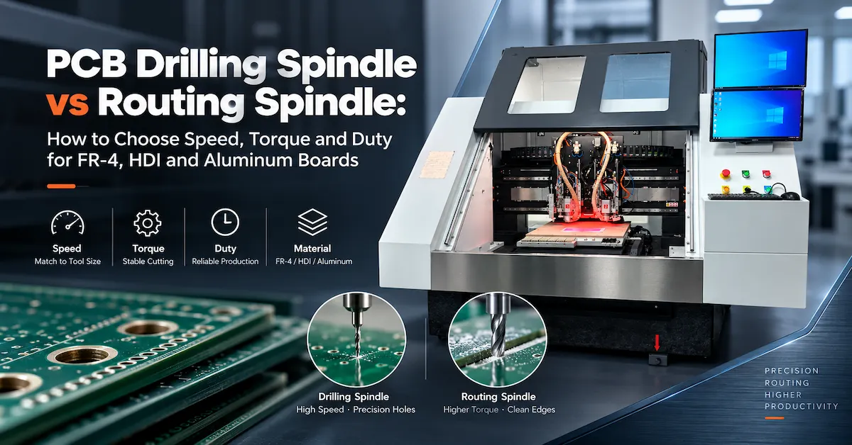
1 Drill 1 Route PCB Machine with CCD
This machine combines:
- Dedicated drilling spindle
- Dedicated routing spindle
- CCD vision alignment
- Automatic fiducial recognition
- Automatic tool management
It is suitable for:
- PCB contour routing
- Precision board processing
- FR4 PCB
- Flex PCB
- Rigid-flex PCB
- Aluminum PCB
Product link:
Buyer Checklist Before Requesting a Quote
| Information | Example |
|---|---|
| PCB Material | FR4, flex, rigid-flex, aluminum PCB |
| Board Size | Panel dimensions |
| Routing Requirement | Outline, slot, opening |
| Alignment Need | Fiducial marks available |
| Accuracy Requirement | Routing tolerance |
| Production Volume | Prototype or batch production |
| Tool Requirement | Router bit size |
| Drilling Need | Yes or no |
| Current Issue | Alignment error, scrap, slow setup |
| Automation Need | Tool change, CCD, detection |
Common Buying Mistakes to Avoid
Mistake 1: Choosing CCD Without Checking Routing Accuracy
CCD improves alignment, but spindle stability and machine structure are equally important.
Mistake 2: Ignoring Fiducial Design
CCD systems need suitable reference marks. Buyers should confirm whether their PCB design supports vision alignment.
Mistake 3: Comparing Only Camera Specifications
A good CCD routing machine requires:
- Camera
- Software
- Motion system
- Spindle
- Fixture
All components work together.
Mistake 4: Not Testing Real Boards
Sample processing is recommended before purchase, especially for precision routing applications.
Mistake 5: Forgetting Tool Management
Routing quality changes when tools wear. Tool detection and replacement planning are important.
FAQ: CCD Routing Machine
1. What is a CCD Routing Machine?
A CCD Routing Machine is a PCB CNC routing machine equipped with camera vision alignment to automatically detect board position before routing.
2. Why is CCD useful for PCB routing?
CCD helps correct PCB placement errors and improves contour routing accuracy, especially for precision boards.
3. Can CCD routing reduce PCB scrap?
Yes. Automatic alignment reduces routing deviation caused by panel placement errors.
4. What PCBs are suitable for CCD routing?
CCD routing is suitable for FR4, multilayer PCB, flex PCB, rigid-flex PCB, and aluminum PCB applications.
5. Does CCD replace mechanical accuracy?
No. CCD works together with spindle stability, machine rigidity, fixture design, and software control.
6. Can CCD routing support drilling?
Some machines combine drilling and routing functions with CCD alignment, such as CHIKIN CNC’s 1 Drill 1 Route PCB Machine with CCD.
7. What affects CCD recognition accuracy?
Camera resolution, lighting, fiducial quality, software compensation, and board surface conditions affect recognition.
8. What should I provide before quotation?
Provide PCB material, size, routing requirement, fiducial information, accuracy target, and production volume.
Conclusion: CCD Routing Improves PCB Processing Accuracy
A CCD Routing Machine helps PCB manufacturers achieve more accurate contour processing by combining CNC routing with automatic vision alignment.
For factories producing precision PCB shapes, multilayer boards, rigid-flex products, or high-mix orders, CCD routing can reduce alignment errors, improve production consistency, and lower scrap.
CHIKIN CNC provides PCB drilling and routing solutions for manufacturers that need accurate, flexible, and reliable board processing.
If you are comparing CCD Routing Machine options, send your PCB material, board size, routing requirements, fiducial information, and accuracy target. CHIKIN CNC can help recommend a suitable configuration.
Contact CHIKIN CNC to request a CCD routing machine solution and quotation: