
Hardware Bug of Battery Sampling Circuit Prototype
Jan 23, 2025
As the saying goes, "It's OK if the circuit and I can run. If the circuit doesn't run, I will run." Today's issue brings a hardware bug of a group member. Without further elaboration, let's take a look: Problem description: The product battery sampling circuit prototype has a probability of 40uA additional leakage current. One of the five prototypes has this abnormal phenomenon. The problem is located on the PMOS, and replacing the PMOS is helpful. The circuit schematic is as follows:
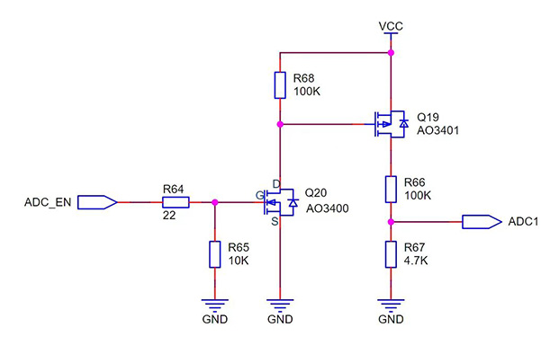
When ADC_EN is high, NMOS tube Q20 is turned on, PMOS tube Q19 is turned on, and ADC1 collects the voltage of VIN (ADC1≈VCC*4.7K/104.7K). When ADC_EN is low, both NMOS and PMOS are turned off, and there will be no leakage current on R66 and R67 (necessary circuit for low power consumption).

According to the schematic diagram, there is no problem, but the actual abnormality is that when Q19 is turned off, there is still a leakage current of 40uA. Cause analysis: After carefully checking the VIN voltage with group friends, it was found that the battery voltage corresponding to VIN is a 12V battery, that is, the voltage of the battery will be higher (greater than 12V) after it is fully charged. And this schematic diagram is copied from the 4.2V lithium battery collection circuit. . .
When NMOS is turned on, the VGS voltage at both ends of PMOS is almost equal to VIN (greater than 12V), and the PMOS used is AO3401, and its VGS withstand voltage absolute maximum is ±12V. In addition, the problem will be solved after replacing PMOS as described above, so it is suspected that the VGS overvoltage of PMOS causes internal damage to PMOS, which may generate additional leakage current.


Recent Posts

October 26, 2016
The Most Successful Engineering Contractor


May 12, 2025
China PCB Drilling Routing machine Development
May 06, 2025
PCB Design Process and Key PointsCONTACT US
Contact US
Product Information
Quantity
Unit
Piece
Support order samples, customization, wholesale direct, and complete payment. If the product you look for does not have corresponding customized content, pls fill out the form below to contact us, and we will reply ASAP.