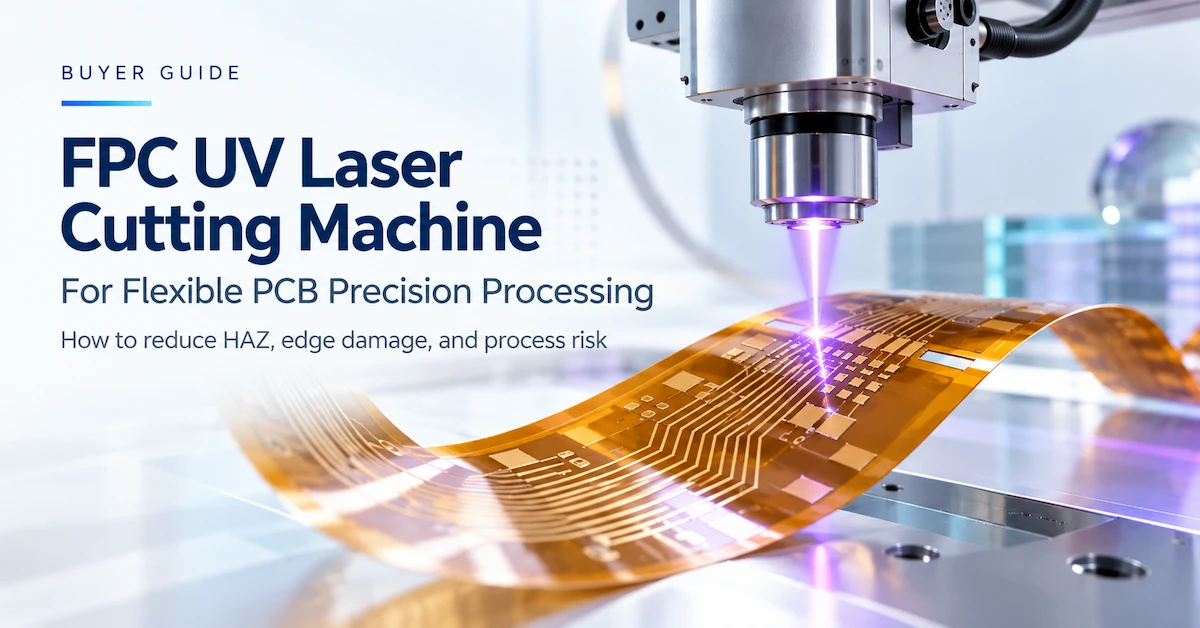




An FPC UV laser cutting machine is a precision processing system designed for flexible printed circuits, coverlay films, and selected thin electronic substrates. Unlike mechanical routing or die cutting, UV laser processing removes material without direct cutting-tool contact, making it particularly attractive for intricate outlines and delicate substrates.
For electronics manufacturers, the main advantage is not simply laser power. It is the ability to achieve acceptable cutting quality, accurate registration, and repeatable production while controlling thermal effects and material deformation.
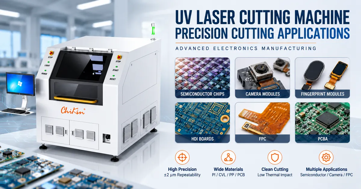
The CHIKIN CNC CK-PP30-6060-DA combines a 355nm picosecond UV laser, linear motor motion, CCD-assisted positioning, and vacuum workpiece fixation. Its published specifications provide a useful starting point for evaluating FPC cutting and depaneling applications.
However, the purchasing decision should ultimately depend on sample cutting results, material compatibility, verified dimensional accuracy, and production throughput.
This guide explains how to evaluate the machine, understand its specifications, establish acceptance criteria, and prepare a technically complete request for quotation.
1. What Is an FPC UV Laser Cutting Machine?
An FPC UV laser cutting machine uses focused ultraviolet laser pulses to remove material along programmed cutting paths.
In flexible printed circuit manufacturing, this process can support contour cutting, coverlay processing, openings, and selected panel separation operations.
Flexible circuit constructions may contain polyimide (PI), copper conductors, adhesives, protective films, and other materials. These layers differ in their response to cutting forces and laser energy.
Conventional mechanical processes can introduce contact pressure, vibration, tooling wear, and deformation. Laser processing eliminates direct mechanical cutting forces at the workpiece, although heat-affected regions and process residues must still be controlled.
Why Is 355nm UV Laser Technology Used?
The 355nm wavelength is commonly evaluated for fine processing of polymer-based electronic materials.
Its relatively short wavelength can provide favorable absorption and localized energy delivery in suitable substrates. Combined with picosecond pulses, it offers a way to process delicate features while limiting thermal diffusion under appropriately optimized conditions.
Nevertheless, a UV laser is not a cold-cutting process. Excessive energy accumulation can still cause discoloration, carbonization, adhesive damage, or delamination.
The correct objective is a validated process window that meets finished-part requirements, not an unsupported promise of zero thermal damage.
2. Who Should Consider UV Laser Cutting for Flexible Circuits?
This type of equipment is particularly relevant to factories processing thin, delicate, or geometrically complex electronic materials.
| Buyer Segment | Typical Application | Primary Purchasing Concern |
|---|---|---|
| FPC manufacturers | Flexible PCB outlines and openings | Edge quality and deformation |
| Coverlay processors | Cover film trimming and openings | Accurate feature placement |
| Flexible electronics suppliers | Thin circuit substrates | Material compatibility |
| Camera module manufacturers | Flexible interconnect components | Fine geometry and handling |
| Fingerprint module suppliers | Sensor-related flexible circuits | Registration and dimensional consistency |
| HDI PCB manufacturers | Selected fine-feature processing | Thermal influence and copper protection |
| PCBA manufacturers | Suitable populated-board separation tasks | Component clearance and process stress |
| Electronics R&D laboratories | Prototypes and changing designs | Fast program changeover |
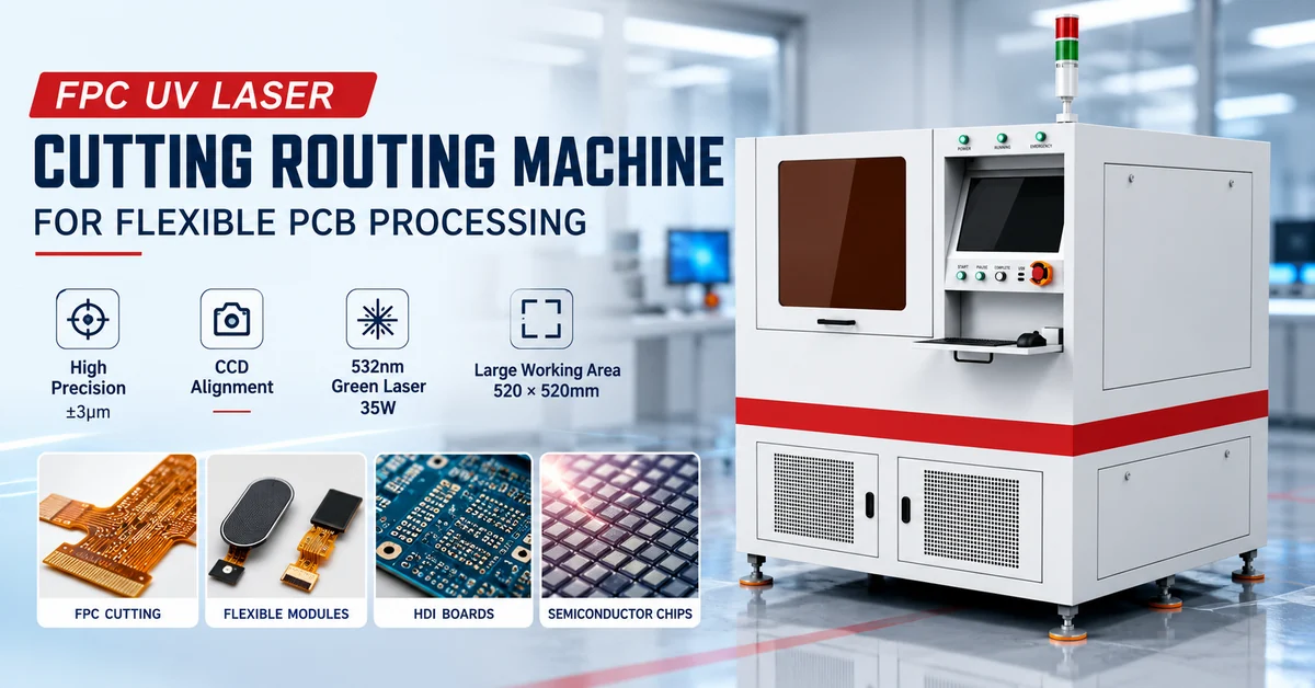
The equipment's promotional material also identifies semiconductor chips, camera modules, fingerprint modules, HDI boards, FPC, and PCBA as application directions.
These should be understood as potential application sectors, not confirmation that the machine can cut every associated material.
For example, cutting an FPC interconnect used inside a camera module is different from directly cutting a semiconductor wafer.
The manufacturer's material specification and actual sample testing must establish whether the intended operation is supported.
3. CHIKIN CNC CK-PP30-6060-DA: Technical Specifications
Shenzhen ChiKin Automation Equipment Co., Ltd. offers PCB manufacturing and precision processing equipment, including laser cutting solutions for flexible electronic materials.
The CHIKIN FPC UV Laser Cutting Routing Machine is positioned for non-contact processing of delicate flexible circuit constructions.
Published CK-PP30-6060-DA Specification Table
| Technical Parameter | Published Specification |
|---|---|
| Model | CK-PP30-6060-DA |
| Laser technology | UV picosecond laser |
| Wavelength | 355nm |
| Laser output | 30W at 1000kHz |
| Pulse frequency range | 300–1200kHz |
| Pulse width | Less than 15ps |
| Laser beams | Single beam |
| Processing accuracy | ±25μm |
| Maximum processing area | 550 × 550mm |
| Non-metallic material thickness | ≤0.5mm |
| Workpiece fixing | Vacuum adsorption |
| Motion drive | Linear motors |
| X/Y maximum motion speed | 400mm/s per axis |
| X/Y maximum travel | 610 × 610mm |
| X/Y positioning accuracy | ±8μm |
| X/Y repeatability | ±2μm |
| CCD cameras | 1 |
| CCD field of view | 4.5 × 5.5mm |
| CCD alignment accuracy | ±6μm |
| Galvanometer scanning range | 40 × 40mm |
| Focus spot size | 16–30μm |
| Equipment air supply | 0.7MPa |
| Operating interface | Chinese / English |
These are published equipment specifications, not independently verified machining results. Processing performance depends on material, configuration, setup, and acceptance conditions.
Important: Confirm the Effective Processing Area
The promotional material describes a 600 × 600mm working area, while the detailed machine specification lists 550 × 550mm maximum processing area.
These figures should not be treated as interchangeable.
Before purchasing, ask CHIKIN CNC to confirm the effective laser processing envelope for the quoted configuration, including usable fixture space, edge clearance, and any limitations created by the workholding arrangement.
The detailed specification should be used as the preliminary engineering reference until a final approved drawing is supplied.
Similarly, promotional materials mention 15W, 20W, and 30W laser options, whereas the CK-PP30-6060-DA specification identifies a 30W source. Availability and performance of alternative power configurations should be confirmed individually.
4. Understanding Accuracy: Why ±2μm Repeatability Is Not ±2μm Cutting Accuracy
One of the most important aspects of sourcing a precision laser cutting machine is distinguishing different measurement terms.
Manufacturers may publish motion accuracy, repeatability, CCD alignment accuracy, and overall processing accuracy.
These figures describe different capabilities.
| Accuracy Metric | Published Value | What It Describes |
|---|---|---|
| X/Y positioning accuracy | ±8μm | Accuracy of commanded axis positioning |
| X/Y repeatability | ±2μm | Consistency when returning to a commanded position |
| CCD alignment accuracy | ±6μm | Performance of the vision alignment process |
| Processing accuracy | ±25μm | Published overall processing accuracy |
A machine with ±2μm repeatability does not automatically manufacture finished FPC parts within ±2μm.
Finished-part accuracy may also be influenced by focus adjustment, material distortion, thermal effects, vision registration, workholding, cut geometry, and software compensation.
These specifications should not simply be added together to calculate a finished-part tolerance.
Instead, buyers should define actual acceptance criteria for the finished component and request dimensional measurements from representative cut samples.
For FPC manufacturers producing fine outlines and closely spaced features, this distinction is essential to avoiding costly specification misunderstandings.
5. What Materials Can the FPC UV Laser Cutting Machine Process?
The CK-PP30-6060-DA specification identifies cover film (CVL), FPC outline processing, auxiliary materials, PCB fiberglass, PP, and PI among its processing directions.
The specified non-metallic material thickness limit is ≤0.5mm.
However, material compatibility must be evaluated at the complete stack level.
Material and Application Comparison
| Material or Structure | Processing Objective | Key Risk to Validate |
|---|---|---|
| Polyimide (PI) film | Fine contours and openings | Discoloration and heat-affected zone |
| FPC coverlay (CVL) | Coverlay profiling and window processing | Adhesive damage and residue |
| Thin flexible circuit | Outline processing and separation | Copper damage and dimensional distortion |
| PP and auxiliary films | Selected film-processing tasks | Melting, debris and cut consistency |
| PCB fiberglass material | Application-specific cutting | Edge quality and incomplete penetration |
| Copper-clad flexible laminate | Selected contour or separation tasks | Different laser response across layers |
| Rigid-flex PCB | Processing of qualified thin sections | Delamination and rigid/flexible transitions |
| Populated PCBA | Qualified component-adjacent separation | Clearance, thermal impact and fixture access |
The published thickness limit specifically refers to non-metallic materials. It should not be interpreted as a guaranteed 0.5mm cutting capacity for every copper-containing multilayer construction.
For copper-clad and other composite workpieces, the complete stack must be tested.
Why Material Stack-Up Matters
A flexible circuit may include polyimide, adhesive, copper foil, coverlay, and protective coatings.
Each layer can respond differently to the same laser settings.
A parameter combination that cuts bare PI film successfully may not provide acceptable results on an FPC containing copper and adhesive layers.
For this reason, purchasing teams should provide actual material samples and cross-sectional stack information rather than simply describing the material as "flexible PCB."
6. How Does the 355nm Picosecond Laser Processing System Work?
The machine combines an ultraviolet laser source, galvanometer scanning, precision motion, camera alignment, and vacuum fixation.
A typical qualified workflow includes the following stages.
Step 1: Import Cutting Data
The operator prepares the required contour or processing program.
Machine-specific CAD/CAM file compatibility and supported file formats should be confirmed during technical evaluation.
Step 2: Fix the FPC Workpiece
The vacuum adsorption system helps hold thin materials in position.
Workpiece flatness, vacuum distribution, fixture openings, and substrate stiffness must be evaluated to prevent movement during processing.
Step 3: Perform CCD Alignment
The CCD system identifies suitable reference features and supports alignment of the cutting program to the actual board.
The published camera field of view is 4.5 × 5.5mm, with a specified alignment accuracy of ±6μm.
Buyers should verify compatibility with their fiducial size, surface appearance, lighting conditions, and panel layout.
Step 4: Execute Laser Cutting
The 355nm picosecond laser follows the programmed processing path.
The published galvanometer scanning range is 40 × 40mm, while the machine provides a larger motion platform.
For processing patterns spanning a larger area, buyers should confirm how galvanometer scanning and stage movement are coordinated, including any field-transition errors.
Step 5: Inspect the Finished Parts
After cutting, operators check critical dimensions, edge condition, residual material, and any thermal influence.
Production approval should be based on representative batches rather than a single visually acceptable sample.
7. UV Laser Cutting vs Mechanical Routing vs Die Cutting
A UV laser cutting machine is not automatically the best solution for every flexible circuit.
The correct technology depends on the material, geometry, production volume, dimensional requirements, and allowable process risk.
| Evaluation Factor | UV Picosecond Laser | Mechanical Routing | Die Cutting / Punching |
|---|---|---|---|
| Tool contact | Non-contact | Direct contact | Direct contact |
| Tool wear | No conventional cutting-bit wear | Router-bit wear | Die wear |
| Complex contours | Programmable | Programmable within cutter limits | Dedicated tooling required |
| Mechanical loading | Low cutting-tool contact force | Cutting forces present | Pressing and shearing forces |
| Thermal influence | Requires validation | Generally no laser-induced HAZ | Generally no laser-induced HAZ |
| Design changes | Program adjustment | Toolpath adjustment | May require new tooling |
| Thin flexible materials | Often advantageous when qualified | Support and deformation concerns | Appropriate with validated tooling |
| Main cost drivers | Equipment, laser system, processing time | Tools, maintenance, machine time | Dies, maintenance, production volume |
When Is UV Laser Cutting the Better Choice?
It is especially worth evaluating when the production line processes delicate flexible films, intricate outlines, or frequently changing designs that make dedicated mechanical tooling expensive.
When Might Mechanical Processing Be Better?
CNC routing may remain economical for suitable rigid boards and contours where tool contact does not create unacceptable damage.
Die cutting can also be efficient for stable high-volume products when dedicated tooling costs are justified.
For broader comparison, explore CHIKIN's PCB laser cutting equipment range and its PCB drilling and routing solutions.
The best technology is the one that meets the required quality at an acceptable production cost.
8. How to Evaluate Cutting Quality and Heat-Affected Zones
Cutting quality should be evaluated using measurable criteria rather than general descriptions such as "perfect edges" or "zero damage."
Even picosecond laser systems can produce thermal effects if the process parameters are unsuitable.
A research paper published in Optics and Lasers in Engineering in 2020, titled "Fine pitch features laser direct patterning on flexible printed circuit board," examined laser processing of copper on polyimide substrates and emphasized the importance of minimizing substrate damage through parameter optimization.
This supports a practical purchasing principle: laser source selection alone does not guarantee the required finished-part quality.
Recommended Quality Inspection Checklist
| Quality Parameter | What to Inspect | Why It Matters |
|---|---|---|
| Cut-edge condition | Burrs, discoloration, irregular edges | Affects appearance and downstream handling |
| Heat-affected zone | Width and appearance of thermal alteration | Indicates potential damage near the cutting path |
| Dimensional accuracy | Finished outline and critical opening dimensions | Determines drawing conformity |
| Copper integrity | Trace damage or unwanted material removal | Protects circuit functionality |
| Adhesive condition | Residue, bubbles, recession or separation | Supports laminate integrity |
| Delamination | Layer separation near processed edges | May affect reliability |
| Registration accuracy | Feature location relative to fiducials | Important for high-density layouts |
| Electrical performance | Continuity and insulation where relevant | Confirms circuit functionality |
For flexible printed boards, IPC-6013E, Qualification and Performance Specification for Flexible and Rigid-Flexible Printed Boards, provides a recognized industry framework that may be referenced alongside the applicable customer requirements.
A machine's laser specifications do not themselves establish compliance with this board-performance standard.
The final inspection requirements should be agreed between buyer and supplier before qualification.
9. Does a 30W Laser Mean Higher Production Throughput?
Not necessarily.
Laser output power affects the available processing capability, but actual production output depends on material removal requirements, cutting-path length, number of passes, alignment, handling, and inspection.
The CK-PP30-6060-DA specification lists 30W output at 1000kHz and a pulse-frequency range of 300–1200kHz.
Its published X/Y maximum motion speed is 400mm/s.
Maximum axis motion speed is not the same as validated laser cutting speed.
For realistic capacity planning, use:
Production Cycle Time = Loading + Alignment + Cutting + Unloading + Required In-Cycle Checks
Then evaluate:
Accepted Output per Hour = Actual Completed Panels per Hour × Acceptance Rate
The correct RFQ should ask for a cutting demonstration using the buyer's actual FPC panel and defined quality criteria.
Do not estimate full-shift productivity by multiplying the maximum axis speed by production hours.
10. Factory Acceptance Test: What Should Buyers Verify Before Shipment?
A Factory Acceptance Test (FAT) is particularly important for precision laser processing equipment because machine motion specifications do not completely describe cutting performance.
A practical FAT should include:
-
Material verification: Confirm the tested samples match the buyer's production stack-up.
-
Dimensional inspection: Measure finished outlines, openings, and registered features.
-
Thermal inspection: Evaluate discoloration, residues, and the heat-affected zone.
-
CCD evaluation: Check fiducial recognition and repeated alignment.
-
Workholding evaluation: Confirm vacuum fixation for the intended material and panel geometry.
-
Cycle-time validation: Measure the complete operating cycle.
-
Repeatability checks: Compare results across multiple parts and relevant panel positions.
-
Safety and utility verification: Check guards, interlocks, extraction, electrical supply, and applicable documentation.
-
Software demonstration: Verify program loading, operating modes, alarms, and required file compatibility.
-
Documentation review: Confirm maintenance information, service scope, spare parts, and contractual acceptance records.
Published Installation and Utility Requirements
| Item | CK-PP30-6060-DA Specification |
|---|---|
| Machine dimensions | 1550 × 1800 × 1800mm |
| Machine weight | Approximately 2500kg |
| Main equipment supply | AC220V, 50–60Hz |
| Published main equipment power | 5kW |
| Listed vacuum cleaner supply | AC220V, 50–60Hz, 1.5kW |
| Compressed air | 0.7MPa |
| Specified operating temperature | 22 ± 2°C |
| Operating interface | Chinese / English |
Buyers should confirm the final electrical configuration, auxiliary equipment scope, extraction capacity, floor-loading requirements, and installation conditions.
Laser safety should also be reviewed against applicable requirements, such as IEC 60825-1 for laser product classification and safety.
An enclosed cabinet alone does not demonstrate a particular laser safety classification. Relevant safety documentation and interlock performance should be checked for the delivered configuration.
11. What Determines FPC UV Laser Cutting Machine Price?
Industrial buyers should compare total ownership cost instead of selecting a machine based only on the initial quoted price.
Cost differences may reflect laser source specification, vision components, motion-system configuration, fixture design, extraction, software, automation, and service arrangements.
Main Purchasing Cost Factors
| Cost Factor | What to Confirm |
|---|---|
| Laser configuration | Exact source, output and pulse specifications |
| Effective working area | Approved processing envelope |
| Motion platform | Linear motor configuration and motion performance |
| CCD alignment | Camera setup and achievable registration results |
| Workholding | Standard vacuum platform and special fixtures |
| Extraction | Included equipment, filters and ventilation requirements |
| Software | Supported formats, licenses and future upgrades |
| Installation | Training, commissioning and acceptance scope |
| Maintenance | Laser-source support, optics and consumables |
| Warranty | Covered parts, duration, exclusions and response terms |
Because the promotional material identifies multiple laser power options, quotations should clearly specify which version is being offered.
Likewise, the distinction between the advertised 600 × 600mm working area and the detailed 550 × 550mm processing area should be resolved before purchase.
A lower initial price is not necessarily advantageous if the selected configuration fails to meet the required panel size, cut quality, or accepted production throughput.
12. Custom Configuration and RFQ Checklist for FPC Manufacturers
The suitability of an FPC UV laser cutting machine depends on the actual manufacturing task.
Possible configuration discussions may involve vacuum fixtures, panel support, CCD alignment, extraction, handling arrangements, software requirements, and production-line integration.
These items should be treated as engineering evaluation topics rather than assumed standard or automatically available options.
Before requesting a quotation, provide the following information:
| RFQ Information | Buyer Requirement |
|---|---|
| Application | FPC outline, coverlay opening, film cutting or depaneling |
| Material | PI, CVL, PP, adhesive, copper, or complete stack description |
| Thickness | Minimum, nominal and maximum workpiece thickness |
| Panel dimensions | Overall size and required usable cutting area |
| Drawing | DXF or other available geometry files; supported import format to be confirmed |
| Precision | Required finished-part tolerances and fiducial registration |
| Edge quality | Acceptable discoloration, residue, HAZ and layer damage |
| Throughput | Panels per hour, production shifts and changeover frequency |
| Automation | Manual loading or requested handling integration |
| Installation | Power, compressed air, extraction, temperature and available floor space |
| Documentation | Sample report, FAT criteria, warranty and service requirements |
Request a Technical Evaluation from CHIKIN CNC
CHIKIN CNC provides precision PCB processing equipment for industrial manufacturers, including UV laser cutting solutions for flexible electronic materials.
If you are evaluating the CK-PP30-6060-DA, begin with your actual material stack, drawing, panel dimensions, and required quality results.
Explore the FPC UV Laser Cutting Routing Machine for the equipment overview.
Contact CHIKIN CNC to Discuss Your Application and Request a Quotation
A complete technical inquiry helps establish whether the proposed laser configuration matches your processing and production requirements.
13. Frequently Asked Questions About FPC UV Laser Cutting Machines
1. What is an FPC UV laser cutting machine used for?
It is used for precision processing of flexible circuits, coverlay films, openings, outlines, and selected depaneling applications. Suitability depends on the complete material construction and required cutting quality.
2. Why choose a 355nm picosecond UV laser for FPC?
The short wavelength and picosecond pulse duration can support fine, localized material processing. They are particularly relevant when mechanical cutting forces or thermal effects are concerns, but actual edge quality must be verified through sample testing.
3. Can the CK-PP30-6060-DA cut polyimide films?
Its published processing-material specification includes PI. The detailed sheet states a maximum non-metallic material thickness of 0.5mm. Actual capability should be validated using the buyer's complete material construction.
4. What is the cutting accuracy of the CK-PP30-6060-DA?
The published processing accuracy is ±25μm. The machine separately lists ±8μm X/Y positioning accuracy, ±2μm repeatability, and ±6μm CCD alignment accuracy. These specifications describe different performance characteristics.
5. Does the machine have a 600 × 600mm working area?
Promotional material states 600 × 600mm, while the detailed specification lists 550 × 550mm maximum processing area. Buyers should request confirmation of the effective usable area for the quoted machine.
6. Is UV laser cutting suitable for copper-clad FPC?
It can be evaluated for appropriate copper-containing flexible circuits, but copper, polyimide, and adhesives respond differently to laser energy. Processing results, electrical integrity, and potential thermal damage should be validated on actual samples.
7. Can this machine process assembled PCBA modules?
PCBA is listed among the promotional application directions. However, populated-board processing requires specific validation of component clearance, material stack, thermal exposure, workholding, and final assembly quality.
8. What is the difference between laser depaneling and laser cutting?
Laser cutting is the broader material-processing operation. Laser depaneling specifically separates individual circuits or assemblies from a panel. A machine may support both types of tasks when its configuration and process qualification permit them.
9. How should manufacturers compare 15W, 20W, and 30W laser options?
Compare verified material compatibility, pulse characteristics, edge quality, process stability, and accepted production throughput. The CK-PP30-6060-DA specification identifies a 30W picosecond source; alternative configurations should be confirmed before quotation.
10. What information should I send when requesting an FPC laser cutting machine quotation?
Provide the material stack, panel size, thickness, cutting drawings, finished-part tolerance, edge-quality requirements, production target, and factory utilities. Sample processing and agreed acceptance criteria are especially valuable before finalizing a purchase.
Conclusion
Selecting an FPC UV laser cutting machine requires a detailed understanding of material compatibility, laser characteristics, motion accuracy, vision alignment, cutting quality, and production requirements.
The CHIKIN CNC CK-PP30-6060-DA offers a published configuration featuring a 355nm picosecond UV laser, 30W output, linear motor motion, CCD-assisted alignment, vacuum fixation, and a specified maximum processing area of 550 × 550mm.
These features make it a relevant candidate for precision FPC outlines, coverlay processing, and other qualified thin-substrate applications.
However, successful equipment selection must go beyond catalog specifications. Buyers should verify the actual processing envelope, distinguish repeatability from finished-part accuracy, inspect thermal effects, and evaluate accepted output under representative production conditions.
For flexible circuit manufacturers, the most valuable investment is a system that produces consistently acceptable parts while meeting the factory's real capacity and operating requirements.
CHIKIN CNC supports industrial customers evaluating PCB and flexible electronic manufacturing equipment.
Review the CHIKIN laser cutting equipment portfolio or contact the CHIKIN CNC team for an application-based quotation.
Share your FPC drawings, material samples, processing requirements, and expected production volume to begin a more precise technical discussion.