



SMT Milling Machine for PCB Cutting: A Practical Buying Guide for Automated Board Separation
An SMT Milling Machine is often purchased for one very specific production problem: separating PCB panels with more consistency, less manual stress, and better control over the cutting path. In many electronics factories, depaneling is not just a finishing step. It can affect board edge quality, component stress, operator safety, downstream inspection, and final product reliability. When panel volume grows or board designs become more delicate, manual separation, simple V-cut breaking, or inconsistent routing can become a hidden cost center.
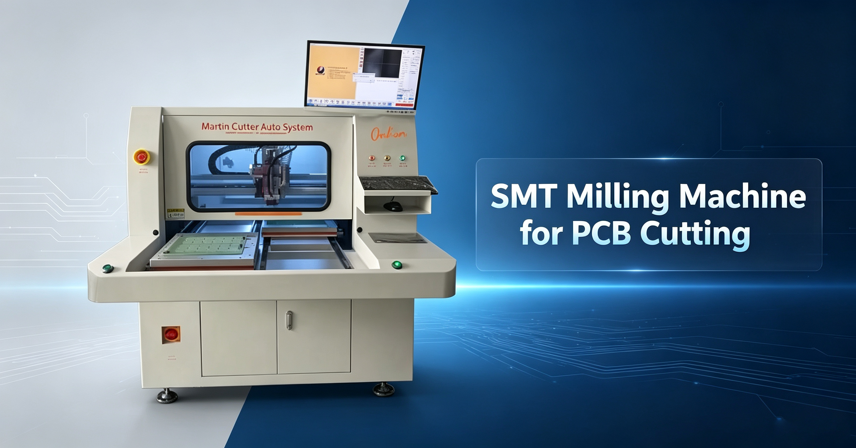
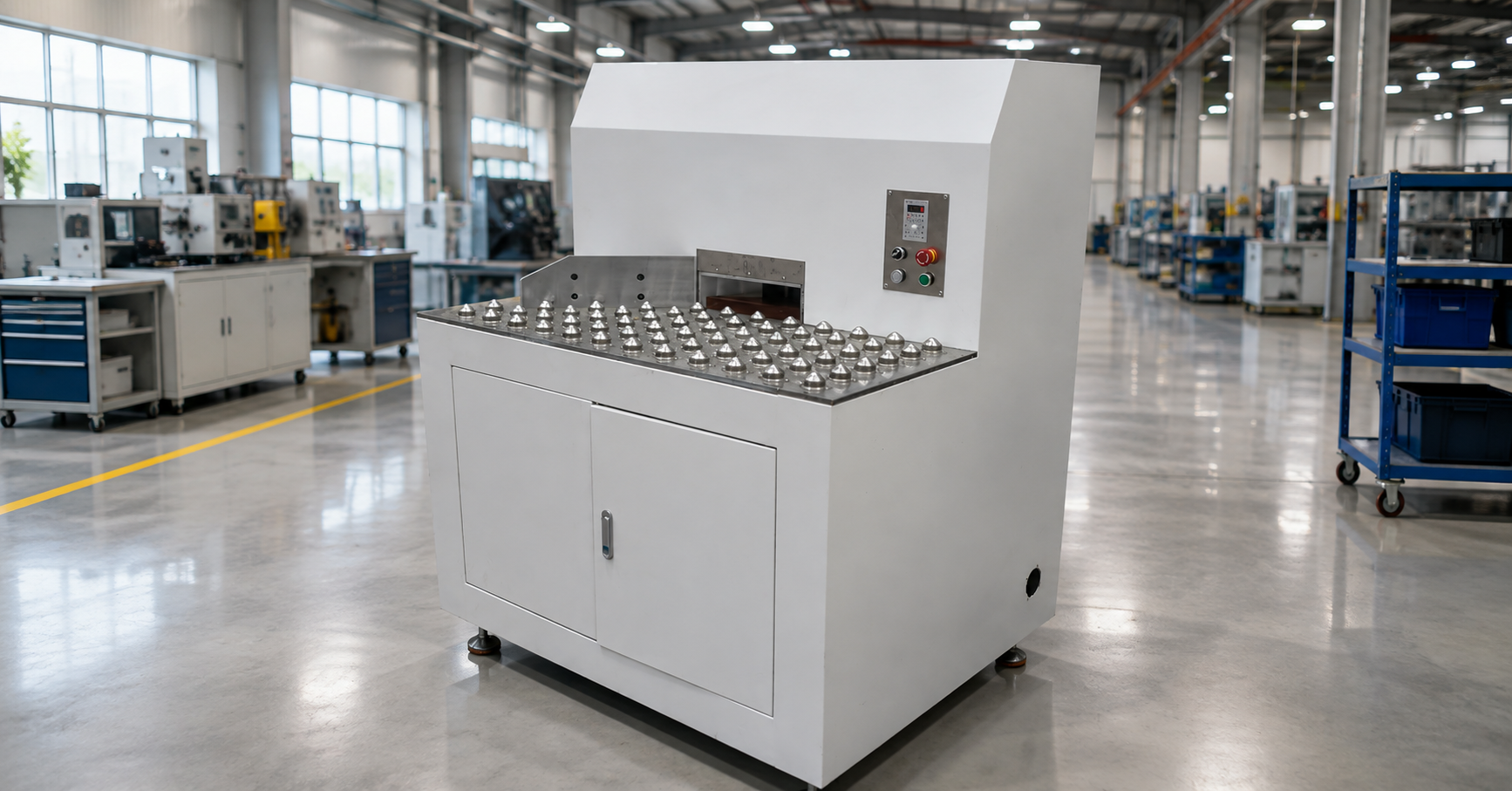
The Chikin CNC product page presents the machine as an SMT Milling Machine for controlled PCB board cutting, with an enclosed work area, monitor-based operation, emergency stop controls, and a flat fixture platform. The specification image identifies the model as CK-MCAS and lists key data such as 8000-10000 rpm spindle speed, pin positioning, Taiwan rail and ballscrew components, DELTA servo system, PIC motion control, adjustable cutting speed from 1-35 m/min, and a maximum machining size of 1250 mm x 630 mm x 3.2 mm.
This article explains what those specifications mean for a procurement team, how an Automatic PCB Cutter fits into an SMT production environment, and what buyers should verify before placing an order. The goal is not to overstate the machine. It is to help production engineers, purchasing managers, and factory owners ask the right questions before selecting a PCB Board Cutting Machine.
Why PCB Cutting Becomes a Production Pain Point
PCB depaneling looks simple from a distance: a finished panel is separated into individual boards. In practice, the process is sensitive. A board may contain mounted components close to the edge, narrow breakaway tabs, dense copper areas, odd shapes, thin materials, or fragile solder joints. If the separation method creates too much mechanical stress, it may introduce cracks, edge burrs, solder joint fatigue, component tilt, or cosmetic defects.
Manual separation can be acceptable for low-volume prototypes, but it depends heavily on the operator. One worker may apply a smooth motion, while another may bend the panel too aggressively. Even when defects are not immediately visible, stress can reduce confidence in the assembly process. In higher-volume production, this variation becomes hard to manage.
A controlled SMT Milling Machine addresses the problem differently. Instead of relying on bending or hand force, it uses a defined cutting path and controlled motion. The board is positioned on a fixture table, the tool follows the programmed route, and the machine repeats the process cycle after cycle. For buyers, the important question is not only whether the machine can cut PCB material. The more practical question is whether it can cut the buyer’s specific panel format, thickness, remaining web, tooling holes, and edge quality requirements.
How an SMT Milling Machine Works in PCB Cutting
The product page describes a machine layout with an enclosed cabinet, a monitor, operator controls, and an internal cutting area. The specification table lists a spindle speed of 8000-10000 rpm, which indicates a rotary cutting process rather than a purely static blade process. The machine uses pin positioning, which usually means the PCB panel is located by reference holes or tooling holes on the fixture. This is important because repeatable positioning is one of the main differences between controlled depaneling and manual separation.
The CK-MCAS specification lists one upper and one lower cutter. In practical terms, buyers should ask how the upper and lower tools interact with the PCB, what cutter geometry is recommended, and how tool wear is monitored. The table also lists a minimum remaining thickness of 0.1 mm, a minimum machining size of 105 mm x 105 mm x 0.4 mm, and a maximum machining size of 1250 mm x 630 mm x 3.2 mm. These numbers matter because board thickness and panel size determine whether the system can handle the current project and future product families.
The motion platform is also central to performance. The listed X, Y, and Z axis rails are from Taiwan, and the ballscrews are also listed as Taiwan origin. X/Y rapid speed is 0-40 m/min, while Z rapid speed is 25 m/min. These are motion specifications, not direct guarantees of finished throughput. Actual cycle time depends on cut length, material, fixture loading, tool diameter, acceleration, operator workflow, and inspection steps.
Core Specifications Buyers Should Review
| Item | CK-MCAS Specification | Why It Matters for Buyers |
|---|---|---|
| Cutter arrangement | Upper and lower cutter | Helps buyers understand cutting mechanics and tooling setup |
| Positioning mode | Pin mode | Supports repeatable panel location when tooling holes are available |
| Spindle speed | 8000-10000 rpm | Relevant to cutting quality, feed rate, and tool/material matching |
| Cutter cooling | Water-cooling | Helps manage heat during cutting and supports process stability |
| X/Y/Z axis rail | Taiwan | Indicates motion hardware category, useful for maintenance discussion |
| X/Y/Z axis ballscrew | Taiwan | Affects positioning, motion stability, and service planning |
| X/Y rapid speed | 0-40 m/min | Useful for estimating non-cutting movement and cycle potential |
| Z rapid speed | 25 m/min | Important for vertical approach and retract movement |
| Processing progress indicator | ±0.05 mm | Buyers should confirm whether this refers to accuracy, repeatability, or display indication |
| Machine material | Granite | May support vibration resistance and dimensional stability |
| Servo system | DELTA | Known industrial control component, useful for spare-part planning |
| NC system | PIC motion control | Buyers should verify software workflow and file compatibility |
| Operating interface | Chinese / English | Important for international operator training |
| Air cylinder | SMC | Pneumatic component brand, relevant to reliability and sourcing |
| Solenoid valve | SMC | Helps maintenance teams identify replacement channels |
| Maximum machining size | 1250 x 630 x 3.2 mm | Defines the upper range of compatible panel dimensions |
| Minimum machining size | 105 x 105 x 0.4 mm | Defines the lower range of compatible workpieces |
| Minimum remaining thickness | 0.1 mm | Important for tab, web, and partial-depth cutting strategy |
| Minimum distance of each cut | 15 mm | Affects layout feasibility for dense panel designs |
| Cut speed | 1-35 m/min, adjustable | Supports tuning for material, thickness, and edge quality |
| Minimum distance to hole of pin | 6 mm | Relevant to tooling-hole and route-path layout |
| Air pressure | 0.5 MPa | Must match factory compressed air supply |
| 强度 | 5 kW | Required for electrical planning |
| Power supply | AC 220V | Must match site voltage and electrical standards |
| Machine dimension | L2070 x W2020 x H1600 mm | Useful for floor layout and installation planning |
| Net weight | 3400 kg | Important for floor loading, unloading, and rigging |
| Tool specifications | 120 x 25.4 x 2.0 x 20T, 30T | Buyers should confirm cutter type, lifetime, and replacement cost |
SMT Milling Machine vs Manual PCB Separation
Manual separation has one advantage: low initial investment. For prototypes or small batch runs, it may be sufficient. However, the cost of manual separation is rarely limited to labor. It also includes inconsistent edge quality, operator fatigue, slower repeatability, possible board bending, and weaker process traceability.
An SMT Milling Machine is more suitable when the same panel must be separated repeatedly, when the board edge is functionally important, or when components are close enough to the separation area that uncontrolled bending becomes risky. It does not automatically solve every depaneling issue. If panel design is poor, if fiducial or tooling holes are missing, or if components are placed too close to the cutting path, the machine still needs proper fixture design and process validation.
A fair comparison should include these points:
| Selection Factor | Manual Separation | SMT Milling Machine |
|---|---|---|
| Initial cost | Lower | Higher |
| Operator dependency | 高 | Lower after setup |
| Repeatability | Variable | More consistent when fixture and program are stable |
| Suitability for higher volume | Limited | Better suited to repeated production |
| Board stress control | Often weaker | Generally better when cutting path is controlled |
| Process documentation | Usually limited | Can be tied to programmed routes and setup records |
| Fixture requirement | 极低 | Important for stable results |
| Maintenance | Low equipment maintenance | Requires tool, spindle, motion, air, and cooling checks |
For procurement teams, the decision should be based on total production cost, not purchase price alone. If the line produces expensive assemblies or runs regular batches, the cost of scrap, rework, and operator inconsistency may justify automation faster than expected.
Safety and Risk Control in PCB Cutting Equipment
PCB cutting equipment contains moving axes, rotating tools, sharp cutters, chips or dust, and pinch-point risks. The product page shows an enclosed machine structure and emergency stop controls, both of which are relevant to industrial use. Still, safety cannot be judged from appearance alone. Buyers should ask for details on enclosure interlocks, emergency stop circuit design, access doors, guarding, maintenance modes, dust or chip extraction, and local compliance documentation.
For context, OSHA’s machine guarding rules state that guarding should protect operators from hazards such as point of operation, rotating parts, flying chips, and sparks. OSHA also identifies milling machines as equipment that commonly requires point-of-operation guarding. ISO 12100:2010 provides general principles for machinery safety, including risk assessment and risk reduction across the machine life cycle. These references do not prove that any specific machine is compliant, but they help buyers frame the right safety questions.
In practical purchasing terms, ask the supplier for:
- Guarding and interlock explanation
- Emergency stop layout
- Door opening behavior during operation
- Maintenance access procedure
- Required personal protective equipment
- Dust, chip, or debris control method
- Electrical and pneumatic safety documentation
- Installation and operator training requirements
A buyer should avoid treating safety features as optional accessories. If the equipment will be installed in the United States, European Union, Southeast Asia, or another regulated market, local workplace safety expectations should be checked before purchase.
Where This Automatic PCB Cutter Fits in an SMT Line
An Automatic PCB Cutter is typically used after assembly and inspection steps when the panel must be divided into individual boards. The exact placement depends on the factory process. Some manufacturers cut after reflow and inspection. Others cut after functional testing or after selective coating, depending on board design and handling risk.
The CK-MCAS has a large maximum machining size, which may suit factories that handle bigger panel formats or mixed product families. The machine dimension of 2070 mm x 2020 mm x 1600 mm and net weight of 3400 kg mean it should be planned as fixed production equipment, not a small benchtop device. Facilities should consider unloading route, floor capacity, compressed air availability, electrical connection, exhaust or dust collection layout, and operator access.
The Chinese/English interface is relevant for international buyers because operator adoption is often underestimated. A machine can have strong mechanical capability, but if operators cannot understand alarms, setup screens, or maintenance prompts, productivity will suffer. Before purchase, request interface screenshots, operating video, alarm examples, and training material.
Application Scenarios for PCB Board Cutting
This PCB Board Cutting Machine is most relevant to manufacturers that need controlled separation of PCB panels or similar flat board materials. Based on the product description and specification data, likely application scenarios include:
- SMT production lines requiring repeated PCB panel cutting
- PCB assemblies where manual separation creates unacceptable stress
- Medium to large panel formats within the listed machining range
- Factories needing Chinese/English operation support
- Production cells that require a guarded cutting area
- Boards that can be positioned using pin-mode fixtures
- Product families where adjustable cutting speed is useful for process tuning
However, buyers should verify suitability through samples. A machine category name is not enough. Before mass production, send real panel drawings, material details, board thickness, component keep-out information, and route requirements to the supplier. A sample cutting test can reveal edge quality, burr level, fixture stability, cycle time, and tool wear far better than a brochure.
How to Choose the Right SMT Milling Machine
Start with the panel, not the machine. The best specification is the one that matches the buyer’s product reality. A purchasing team should collect the following information before requesting a quotation:
| Buyer Input | Why the Supplier Needs It |
|---|---|
| Panel length, width, and thickness | Confirms whether the panel fits the machining range |
| Smallest board size | Checks compatibility with minimum machining size |
| Material type | Affects cutter choice, speed, dust, and edge quality |
| Tooling hole location | Determines whether pin positioning is practical |
| Cut path drawing | Allows route feasibility review |
| Component clearance near cut line | Reduces risk of tool collision or stress damage |
| Remaining thickness requirement | Confirms whether 0.1 mm minimum remaining thickness is relevant |
| Production volume | Helps estimate fixture design and automation level |
| Required edge quality | Determines process parameters and tool selection |
| Factory voltage and air supply | Confirms AC 220V and 0.5 MPa air pressure compatibility |
| Language requirement | Confirms Chinese/English operator interface use |
| Safety documentation needs | Supports import, installation, and audit preparation |
Buyers should also ask whether the system supports the file formats used by their engineering team. If the NC system requires manual programming while the factory expects direct CAD/CAM import, that workflow gap can slow production. Also ask how the machine stores programs, whether access levels can be controlled, and whether setup data can be backed up.
Cost Factors Beyond the Purchase Price
The product page does not provide a confirmed selling price, so any serious quotation should be based on configuration and application. For a real procurement decision, consider total cost of ownership rather than only machine price.
Important cost factors include cutter consumption, fixture design, training, spare parts, shipping, installation, electrical preparation, compressed air preparation, cooling maintenance, downtime risk, and after-sales response. A 3400 kg machine also requires proper logistics planning. Rigging, unloading, factory entrance width, and floor load should be checked early.
Cycle time should also be evaluated realistically. A rapid speed of 0-40 m/min does not mean the machine will cut every board at that speed. Actual cut speed is adjustable from 1-35 m/min, and the right setting depends on material, tool, required edge quality, heat, and stability. A slower cut may be preferable if it reduces burrs, tool wear, or board stress.
Quality Checks Before Mass Production
Before approving an SMT Milling Machine for production, buyers should run a structured validation process. The first step is dimensional verification: check whether the separated board meets edge tolerance requirements. The second is visual inspection: look for burrs, delamination, scratches, tool marks, or damaged solder mask near the cut. The third is functional review: confirm that no components, solder joints, or traces are affected by the process.
If the board will be used in automotive, medical, industrial control, aerospace, or high-reliability electronics, validation should be stricter. IPC design standards, such as IPC-2221 and related IPC board design standards, are useful references for PCB design discipline and manufacturability thinking. They do not replace the buyer’s own product specification, but they reinforce the point that panel layout, board construction, and manufacturing method should be considered together.
A practical validation checklist includes:
- Route accuracy
- Edge finish
- Burr level
- Board warpage after cutting
- Component clearance
- Fixture repeatability
- Cycle time
- Tool wear over repeated panels
- Operator loading and unloading time
- Safety behavior during normal and abnormal operation
- Maintenance access
- Spare cutter availability
Procurement FAQ for Buyers
1. What is the main keyword product category for this machine?
The product is best described as an SMT Milling Machine for PCB cutting. It can also be described as an Automatic PCB Cutter, PCB Board Cutting Machine, Automatic PCB Separator, or PCB Board Splitting Machine depending on the buyer’s search intent and production context.
2. What is the model number?
The specification table lists the model as CK-MCAS.
3. What PCB size range can it process?
The listed maximum machining size is 1250 mm x 630 mm x 3.2 mm. The listed minimum machining size is 105 mm x 105 mm x 0.4 mm. Buyers should still confirm usable fixture area, clamp clearance, and actual product geometry before ordering.
4. What spindle speed does the machine use?
The specification table lists spindle speed as 8000-10000 rpm. The suitable speed for production should be confirmed through material and sample cutting tests.
5. What positioning method does it use?
The machine uses pin mode positioning. Buyers should confirm whether their PCB panels have suitable tooling holes and whether the minimum distance from cut path to pin hole meets the listed 6 mm requirement.
6. What is the cutting speed?
The cut speed is adjustable from 1-35 m/min. Actual production speed should be selected based on edge quality, material, tool life, and process stability.
7. What power and air supply are required?
The table lists 5 kW power, AC 220V power supply, and 0.5 MPa air pressure. Before purchase, confirm local voltage, plug standard, compressed air quality, and installation requirements.
8. Is the machine suitable for every PCB panel?
Not automatically. The listed application is PCB material cutting, but real suitability depends on board thickness, panel size, tooling hole location, component clearance, cut path, copper layout near the edge, and required edge quality. Sample testing is recommended.
9. What should I ask the supplier before buying?
Ask for a sample cutting video using similar material, fixture proposal, cutter type, tool life estimate, spare-part list, software workflow, safety documentation, installation guide, training plan, warranty terms, and after-sales response time.
10. Can it support international operators?
The operating interface is listed as Chinese/English, which is useful for international factories. Buyers should request screenshots or a demo to confirm that operators can use the interface comfortably.
Conclusion: A Practical SMT Milling Machine Choice Starts With the Panel
An SMT Milling Machine can be a strong investment when PCB cutting quality, repeatability, and operator control matter more than the lowest upfront equipment cost. The CK-MCAS specification shows an enclosed, floor-standing PCB cutting platform with pin positioning, 8000-10000 rpm spindle speed, DELTA servo system, PIC motion control, adjustable 1-35 m/min cutting speed, and a large maximum machining size of 1250 mm x 630 mm x 3.2 mm.
For buyers, the next step is not simply asking, “How much is the machine?” A better question is: “Can this machine cut my real panel, at my required quality level, with stable cycle time and safe operation?” If you can provide panel drawings, board thickness, material, tooling hole layout, cut path, and target production volume, Chikin CNC can help review whether this SMT Milling Machine is the right configuration for your PCB cutting process.