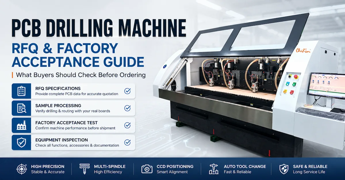




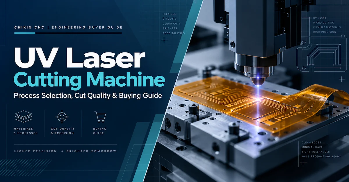
UV Laser Cutting Machine: What Should an Electronics Manufacturer Actually Buy?
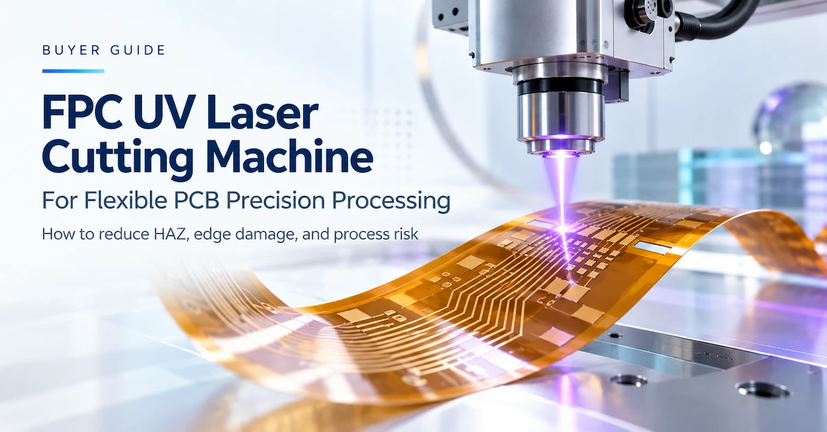
A UV Laser Cutting Machine uses tightly controlled ultraviolet laser energy to remove material along a programmed path. In electronics production, it is often evaluated for fine contours, flexible printed circuits, coverlay, thin polymer films, and selected small-feature processing tasks that are difficult to perform with a contacting cutter. The attraction is not simply a smaller beam: it is the ability to create a repeatable process without applying the cutting force of a router, blade, or punch.
There is an important limitation. Non-contact does not mean heat-free, and UV does not mean universally compatible. A process that produces a good edge on bare polyimide may leave residue on an adhesive-bearing laminate or behave differently near copper. Equally, an accurate motion platform will not guarantee an accurate finished circuit if the sheet moves or the vision registration is inadequate.
The purchasing decision should therefore answer four connected questions: Can the system cut the actual stack-up? Can it meet the finished-part quality specification? Can it do so at the required good-part output? And can the supplier deliver an acceptable factory installation, qualification plan, and service arrangement?
CHIKIN CNC lists UV-based flexible-circuit processing equipment within its Laser Cutting Machine range. Its published FPC product descriptions focus on enclosed, non-contact processing of delicate circuit materials. Machine-specific wavelength, power, working area, accuracy, software functions, and automation options still need confirmation in the final technical quotation.
Start With the Workpiece, Not the Laser Source
Consider three buyers asking for the same product name. The first makes polyimide FPC with copper and adhesive layers. The second needs openings in coverlay film before lamination. The third wants high-volume separation of rigid FR4 boards. These are different engineering problems and should not automatically receive the same machine recommendation.
For a useful RFQ, define the workpiece as a stack rather than a material label. Include base material, layer order, thickness of each functional layer, coatings, copper distribution, support carrier, and whether the product has been laminated or assembled. Add the most difficult feature on the drawing: perhaps a narrow internal slot, an acute corner, a cut close to a conductor, or a contour that crosses materials of different thickness.
Next define what counts as an acceptable part. Some buyers permit slight edge color change provided insulation and strength remain intact. Others need strict limits on char, debris, recession, copper exposure, or laminate separation. The acceptance standard must come from the finished product and end use, not from a generic “clean cutting” promise.
Application fit in one line: UV laser processing deserves evaluation when feature complexity, delicate materials, frequent design changes, or mechanical-force sensitivity justify a controlled optical process. A dedicated die, mechanical router, or V-score separation cell may still be preferable for simple, stable jobs.
Which Materials and Jobs Are Good UV Laser Candidates?
UV systems are widely investigated for polymer-rich electronic substrates, but every combination requires qualification. The categories below describe application directions, not a universal list of materials guaranteed for one CHIKIN model.
| Material or construction | Typical job | Important process risk | Evidence to request |
|---|---|---|---|
| Polyimide film | Fine outline, slot or contour | Char and edge recession | Micrographs and dimensional results |
| Copper-clad flexible laminate | FPC cutting or separation | Trace damage and copper-to-edge clearance | Registered cuts on the finished stack |
| Coverlay with adhesive | Windows and shapes | Adhesive residue and delamination | Edge inspection after the intended process |
| Rigid-flex transition | Selected flexible-region contours | Different layer response | Cross-sections and product-specific tests |
| Thin electronic polymer film | Precision sheet patterns | Melting, curl or shrinkage | Flatness and repeatability tests |
| Thin FR4 construction | Selected openings or depaneling | Resin/glass effects and debris | Stack-specific edge and electrical tests |
| Ceramic or glass-like electronic material | Specialized microprocessing only | Cracking or poor removal efficiency | A separate feasibility study; do not assume compatibility |
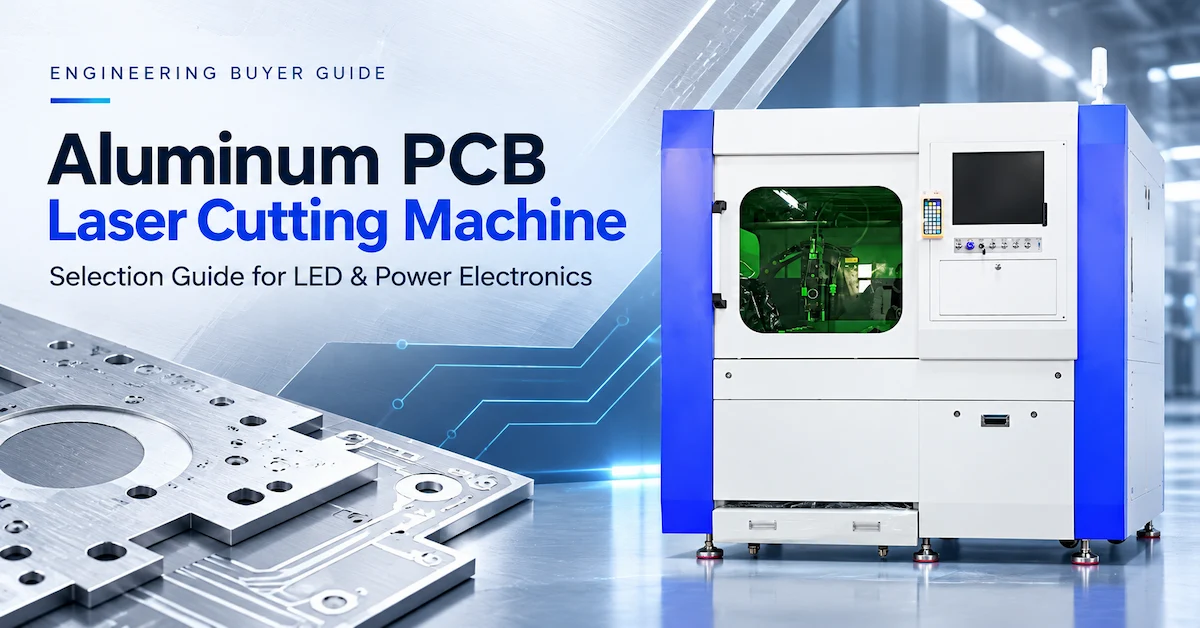
If the requirement is to cut substantial aluminum or copper plate, do not assume an FPC-class UV machine is suitable. CHIKIN also lists metal-processing laser equipment, but these should be evaluated as distinct process families. The broader laser equipment category is a better starting point for such a comparison.
Compare the right laser category
Review CHIKIN’s laser processing options before defining your machine shortlist.
What Makes UV Different From Fiber or CO2 Laser Cutting?
Laser wavelength affects how a material absorbs energy; pulse duration and energy delivery influence how the material is removed. A 355 nm ultraviolet source is a common option in precision industrial processing, while other UV wavelengths and source architectures also exist. Do not assume a specific wavelength is included in a quoted machine until the supplier documents it.
355 nm and Other UV Wavelengths
A 355 nm laser can be produced by frequency conversion of an infrared solid-state source. Its wavelength can be favorable for selected polymers and fine electronic features, but the result depends on the full material and coating system. A different UV wavelength, such as 266 nm, may interact differently with the same surface; that does not automatically make it faster, cleaner, or more economical in production.
Nanosecond and Ultrashort-Pulse Processing
Many industrial UV cutting applications use pulsed operation. Nanosecond and picosecond-class systems differ in how energy is delivered over time. Shorter pulses can reduce some thermal effects in suitable applications, but source cost, removal rate, beam delivery, stability, and maintenance must also be evaluated. Ask for actual edge photographs and throughput on your material, rather than selecting a pulse category in isolation.
UV Versus Fiber
Fiber-based systems are often considered for metal processing, marking, and metal-rich substrates. They should not be treated as drop-in replacements for UV processing of delicate polymer-rich FPC. Nor should an ultraviolet source be assumed to replace a productive metal-plate cutting system. The useful comparison is cost per conforming part on the intended material.
UV Versus CO2
CO2 lasers can process various organic and polymer-based materials. For electronics, wavelength-dependent absorption and thermal response make the actual stack and acceptance requirements especially important. UV may deliver a favorable result in one thin-film application while CO2 or a mechanical process wins on another. Request equivalent sample tests rather than a marketing comparison of theoretical spot size.
The Four Process Parameters That Usually Decide Cut Quality
Operators can adjust many machine settings, but four interacting variables deserve particular attention during process development.
Energy delivered per unit length. Excessive energy can increase thermal damage; insufficient energy may leave uncut material. Merely lowering power is not a complete remedy because scanning speed, focus and the number of passes also change the result.
Focus and spot condition. The effective spot size and energy distribution at the surface influence kerf and feature definition. A slight height difference across a curled film can cause inconsistent results if focus control and fixtures are not appropriate.
Pass strategy. Several controlled passes may be preferable to a single aggressive pass for some laminated constructions. But every additional pass adds time and can also contribute cumulative heating. Compare quality and cycle time together.
Path sequencing. Corners, closely spaced features, overlapping cuts and the order in which parts are separated can change local heat build-up and workpiece stability. An efficient CAM path should preserve the required part support until removal is complete.
No supplier can establish the optimum settings from a generic power specification alone. The practical answer comes from a documented process window and a repeatability study.
Designing a Robust UV Cutting Process Window
A successful demonstration is not the same as a production-ready process. One clean sample may have been produced under carefully selected conditions that do not tolerate normal changes in thickness, flatness, or material lot.
A better qualification sequence has three stages. First, screen a limited set of energy, scan-speed, focus, and pass conditions on representative material. Second, evaluate the promising combinations for edge condition, dimensions, cut completion, and thermal effects. Third, challenge the best candidate using normal material variability and repeated panels.
A modest design-of-experiments approach can be more useful than repeatedly changing one parameter until a sample looks acceptable. Record the actual settings, machine state, material lot and inspection results so engineers can reproduce the work. Include difficult corners, copper-adjacent segments, internal apertures, and the largest production panel—not only a short straight test line.
The release criterion should be a window, not a single perfect point. If a tiny focus change or small film curl makes the product fail, the factory needs better support, compensation, or a different process. That insight can save a costly equipment purchase.
HAZ, Charring, Residue and Delamination: How Should They Be Judged?
HAZ means heat-affected zone: the area adjacent to a cut where the material may have experienced thermal influence. For polymer-rich electronic laminates, the concerns can include color change, decomposition, resin recession, adhesive residue, weak bonding, exposed conductors and loss of edge integrity.
Some effects are visible under appropriate magnification; others require cross-sectional or product-specific tests. A glossy marketing photograph of one cutting edge cannot establish electrical insulation, flex-life performance or long-term reliability. For applications governed by flexible printed-board requirements, IPC-6013 is a relevant family of performance specifications; its requirements must be applied to the correct board construction and customer acceptance class. It is not a certification of a laser machine.
Ask the supplier to define the inspection method: magnification, lighting, measurement calibration, sampling quantity and what qualifies as failure. For an application with copper near the finished edge, include minimum conductor clearance and evidence that the beam did not compromise the laminate. For a bend region, consider whether follow-up mechanical or electrical qualification is needed.
A useful troubleshooting sequence starts with the defect, not with a guess. Incomplete cut may relate to energy, focus, stack variation or debris. Excessive color change may relate to local heating, pulse conditions, path overlap or adhesive chemistry. Edge variation across a sheet may point to focus, flatness or registration. Each diagnosis should be confirmed with controlled trials.
Accuracy Is Not Just a Number on the Motion Specification
A seller may quote axis positioning accuracy, repeatability, scanner resolution or camera positioning precision. These values describe different things. For electronics manufacturers, the key result is often finished-cut position relative to the actual circuit.
A flexible panel can stretch slightly during upstream processing, shift on a carrier, or curl during loading. Even a precise laser will cut the wrong location if the input data and the real panel do not align. Buyers should therefore ask how the system establishes workpiece coordinates and whether vision-based fiducial correction is available in the proposed configuration.
Test registration at several locations, not only near the origin. A large panel can contain local dimensional variation that a simple translation-and-rotation correction cannot eliminate. Document the residual cut-to-pattern error on actual parts. If fiducial recognition fails on low-contrast or coated materials, the process should have a defined recovery method instead of relying on operator improvisation.
Key buyer distinction: stage repeatability, camera recognition repeatability, and finished-circuit dimensional tolerance are not interchangeable. Ask the supplier which one is measured, by what method, and under what conditions.
Fixtures, Vacuum Support and Part Retention
Laser cutting avoids a physical cutting tool, but a thin workpiece still requires careful handling. Polyimide film can curl; coverlay may be tacky; separated pieces may lift or move before the cycle ends. Those effects can dominate scrap generation even when the beam process is stable.
Potential approaches include a suitable vacuum fixture, carrier plate, locating features or a dedicated nest. Each has limitations. Excessive or uneven vacuum can distort material; the carrier may interact with a through-cut beam; pin location may not compensate for sheet-scale distortion. A fixture should preserve flatness, keep debris away from the finished product and allow safe unloading.
Ask what happens at the instant the final cut closes. Does the separated circuit remain supported, move into a waste area, or catch on the carrier? How is it picked up without bending or scratching? How long does fixture changeover take? These questions affect cycle time, yield, downstream assembly and automation more than many brochure features.
For high-mix operations, fixture revision control is also necessary. A correct cutting program paired with the wrong nest can still produce unusable parts.
Software, Gerber/DXF Files and Recipe Management
Industrial buyers frequently assume that the CAM files used by the PCB factory will import directly into every laser workstation. Do not make that assumption. Confirm the exact file formats and software workflow included in the quotation. Gerber, DXF, ODB++ and other formats may require translation or additional modules depending on the system.
The engineering workflow should establish the correct layer, panel orientation, fiducial locations, toolpath offset and revision. The operator workflow should make it difficult to run an obsolete design with an unapproved cutting recipe. Ask whether the equipment supports controlled recipe storage, user permissions, backup, alarm logs and exported process records.
If MES or barcode integration is required, define the data exchange rather than accepting “MES-ready” as a complete specification. Can the machine receive a job identifier? Does it return a pass/fail status, cycle result or traceable recipe number? Is integration standard or custom? What happens if the network is unavailable?
These details are especially valuable to contract manufacturers handling many customer designs and frequent engineering changes.
UV Laser Cutting Versus Mechanical Routing and Die Cutting
UV processing should be justified against feasible alternatives, not chosen because laser technology sounds more advanced.
| Selection factor | UV laser system | Mechanical routing | Dedicated die cutting |
|---|---|---|---|
| Physical cutting force | No contacting cutter | Present | Present |
| Thermal effect | Requires validation | No laser-induced HAZ | No laser-induced HAZ |
| Complex fine contours | Often attractive if qualified | Limited by cutter geometry | Requires suitable die design |
| Engineering revisions | Program/fixture changes | Program/tool/fixture changes | May require new die |
| Consumable/tool wear | Optics and extraction maintenance | Router-bit wear | Die wear and maintenance |
| Stable high-volume simple shape | Cycle-time dependent | Can be competitive | Often attractive after tooling amortization |
| Main proof needed | Stack-specific cut quality | Edge, force, dust and tool life | Edge, deformation and tooling life |
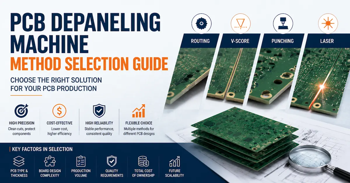
For a conventional rigid-board outline, a PCB Drilling and Routing Machine may be the more economical choice. For straight pre-scored panels, V-CUT may be preferable. The PCB Depaneling Machine Method Selection Guide explores these alternatives in more detail.
The proper question is not “Which technology is best?” It is “Which method meets the product requirement at the lowest acceptable lifecycle cost and risk?”
How to Calculate Real Throughput and Cost per Good Part
Quoting maximum scan speed does not answer how many acceptable circuits a factory will produce. The complete cycle includes loading, locating, vision alignment if used, focusing, multiple cutting passes, extraction, unloading and any required in-cycle checks.
A useful initial equation is:
Gross parts/hour = (3,600 ÷ complete panel cycle in seconds) × finished parts per panel
An illustrative case—not a CHIKIN performance claim—is a panel containing 48 circuits with a 72-second complete cycle. The gross output would be 2,400 circuits per hour. If actual availability were 80% and the conforming-part yield were 97%, the planning output would be approximately 1,862 good circuits per hour. Use this only as a calculation example; real figures require sample trials, line observation and a consistent accounting method.
Check whether the supplier's cycle-time figure includes loading and unloading or only beam-on time. Verify how many passes were used and whether the material, cut geometry, quality criteria and fixtures match your product. For multi-product factories, also measure program changeover and first-piece inspection time.
Then estimate cost per good part from equipment depreciation, operators, electricity, cooling, extraction, optics, consumables, spare parts, rejects, maintenance and expected utilization. A faster machine is not necessarily a better investment if its approved process creates more scrap or requires disproportionately expensive maintenance.
A Better Sample-Test Plan: From Feasibility to Production Evidence
Supplier testing should use your own material and released drawing when possible. A generic sample demonstrates that a beam can cut something; it does not demonstrate that your factory can achieve the needed yield.
Send representative panels from the expected thickness range and include the most difficult features. State material lot information and stack-up. Specify the acceptance method before testing, then ask for raw measurements rather than adjectives such as “excellent edge quality.”
| Validation item | Minimum useful evidence | Decision it supports |
|---|---|---|
| Cut completion | Parts fully separated with no unacceptable bridges | Basic feasibility |
| Edge integrity | Magnified images of representative features | Quality acceptance |
| Thermal influence | Defined HAZ/char/recession evaluation | Stack compatibility |
| Finished dimensions | Calibrated measurement against drawing | Geometric capability |
| Registration | Cut-to-fiducial or cut-to-copper data | Placement accuracy |
| Repeatability | Consecutive sample results, not one best part | Production stability |
| Full cycle | Timed load-to-unload sequence | Capacity planning |
| Lot variation | Testing on more than one relevant material lot | Process robustness |
| Downstream performance | Product-specific electrical/bend tests if required | Fitness for use |
Ask the supplier to preserve both pass and fail observations. A documented unsuccessful recipe can help engineers understand the edge of the acceptable process window. A convincing report should connect material, settings, inspection and output—not merely show attractive photos.
Turn drawings into process evidence
Share the real stack-up and acceptance criteria to discuss sample-cutting feasibility.
RFQ Checklist: What to Send a UV Laser Machine Manufacturer
Procurement can reduce avoidable clarification cycles by sending one structured request. It should cover the product, technical limits, production target and delivery scope.
Material and design: substrate names, supplier material codes if available, full laminate stack-up, copper/adhesive/coverlay thickness, coating, finished outline, internal windows and drawing revision.
Dimensional requirement: maximum panel size, minimum feature, critical tolerances, required cut-to-copper clearance, allowable kerf and flatness conditions.
Quality requirement: acceptable residue, color change, char, delamination, debris, edge roughness, HAZ and any customer-specific electrical or mechanical qualification.
Output requirement: good circuits per shift, panel mix, expected operating hours, changeovers, future programs and acceptable manual handling.
Factory requirement: power supply, floor space, access route, cooling, exhaust connection, material handling, software integration, country of installation and training expectations.
Commercial requirement: itemized machine scope, sample-testing deliverables, FAT, spare-parts kit, packaging, logistics responsibility, installation, warranty terms and after-sales support.
When asking about a CHIKIN configuration, begin with the public FPC UV Laser Cutting Routing Machine description, then request a configuration proposal matched to your material. The company website does not establish one universal source power, working size or tolerance for all possible builds, so these should be confirmed in writing.
FAT and Commissioning: The Acceptance Criteria That Prevent Disputes
A factory acceptance test (FAT) should prove that the specific ordered configuration meets agreed machine and process requirements before shipment. A site acceptance test (SAT), where contracted, should confirm appropriate performance after installation under the agreed site conditions.
For FAT, verify the source and optics specified in the quotation, work area, software license, recipe handling, fixtures, enclosure, interlocks, cooling and extraction interface. Run the agreed customer sample and record dimensions, cut-to-pattern registration, edge quality, thermal effects, repeatability and full cycle time. Confirm manuals, process recipes, backups, maintenance guidance, spare-parts lists and training deliverables.
For commissioning, check local electrical characteristics, floor stability, access, exhaust routing, cooling, material handling and permitted machine operating conditions. Define who supplies each utility and who performs each installation task. A machine can meet factory tests and still experience site problems if extraction or fixture handling is different from the validated setup.
Safety deserves its own documented review. ISO 11553-1:2020 addresses laser-processing machine radiation hazards and related manufacturer information, while IEC 60825-1 covers laser product classification and safety matters. Referring to these standards does not imply that any particular model carries a certification. Ask for current machine-specific evidence appropriate to the destination market.
How to Judge the Supplier Behind the Equipment
An equipment manufacturer earns trust by explaining limits as clearly as capabilities. A useful supplier review considers five areas.
Application engineering. Can engineers explain why a recipe works for your actual stack? Can they identify materials or tolerances that are not yet qualified?
Evidence quality. Do reports contain finished-part dimensions, edge inspection, registration and repeatability? Are test conditions stated clearly?
Configuration transparency. Does the quotation distinguish standard functions from options such as advanced CCD correction, automatic loading, extra software or custom fixtures?
Manufacturing and service. Are installation, training, support contact, consumables and critical spare-part responsibilities documented? How are failures diagnosed and what can be repaired locally?
Lifecycle planning. Can the supplier discuss optic cleaning, extraction filters, cooling maintenance, calibration intervals, software backups and future spare-part availability?
CHIKIN describes its manufacturing focus and background on its About Us page and provides service information through Service Advantages. Treat published corporate information as a starting point; confirm application-specific warranties, options and delivery promises in the quotation rather than inferring them from general marketing statements.
Where CHIKIN UV Laser Equipment Fits in a PCB Production Line
For a flexible PCB factory, laser contouring is not an isolated purchase. It must fit upstream material preparation and downstream inspection, handling and assembly. A good production plan considers which process creates the panel datum, whether the laser cut occurs before or after particular lamination steps, how the carrier is used and where finished circuits are inspected.
CHIKIN's published FPC UV equipment is positioned around non-contact processing of delicate flexible circuits. That may be relevant when a factory is struggling with edge deformation, changing contours, small-part handling or mechanical-tool limitations. Review the two available product presentations for the flexible-PCB processing configuration and the precision flexible-circuit processing configuration.
If the job instead involves thick rigid boards, metal-core plate or other substrates, request a separate process recommendation. The existing Laser Cutting Machine Buying Guide covers the wider family of laser technologies, while this article focuses on UV process selection and qualification.
Check the flexible-circuit configuration
See the published FPC UV processing direction and prepare configuration questions.
Ten Buyer Questions Before You Approve the Machine
1. Is UV laser cutting suitable for all PCB materials?
No. Suitability depends on the material stack, thickness, copper distribution, coatings, required feature and finished-edge acceptance. UV systems deserve evaluation for selected thin and polymer-rich electronics materials, but actual processing must be proved on representative samples.
2. Is 355 nm always the best UV wavelength?
No. A 355 nm source is common in precision processing, but wavelength is only one variable. Pulse behavior, beam delivery, optics, material absorption, removal rate and lifecycle cost can change the preferred configuration. Confirm the exact source offered with the machine.
3. Does UV cutting eliminate HAZ?
No. UV laser cutting remains an energy-based process. A well-developed recipe may reduce unwanted thermal effects in suitable applications, but acceptable char, residue, recession and laminate integrity should be measured against product requirements.
4. How should finished-cut accuracy be specified?
Specify the finished dimension and, when necessary, the cut location relative to circuit features. A stage repeatability number alone is insufficient. Include the inspection method and a sampling plan covering the usable work area.
5. Can a UV system cut adhesive-backed coverlay?
Potentially, but adhesive behavior can be challenging. Validate residue, edge condition, part release and downstream bonding performance on the exact coverlay construction. Avoid transferring a recipe from bare film without testing.
6. What is the difference between galvanometer scanning and stage motion?
Galvanometer systems steer the beam optically; stage systems move the workpiece or optics mechanically. Different architectures have distinct field-size, distortion, acceleration and registration trade-offs. The right choice depends on feature geometry, total field and the tolerance that must be achieved on the part.
7. How should I compare machine throughput?
Measure the complete production cycle and conforming output. Include alignment, multi-pass cutting, load/unload, changeover and rejects. Maximum beam or scanner speed is not equivalent to good parts per hour.
8. What should a supplier sample report include?
At minimum: material identification, released geometry, process conditions, cut-completion evidence, edge photographs, dimensional measurements, registration results, consecutive-part repeatability and complete cycle time. Critical applications may require additional downstream product testing.
9. Which utilities and safety systems matter?
Confirm electrical supply, cooling, ventilation, fume extraction, enclosure, interlocks, operator information and maintenance access for the actual configuration. Appropriate laser-machine safety evidence should be reviewed for the installation market.
10. What information should I send before asking for a quote?
Provide material stack-up, panel dimensions, contour files, critical tolerances, quality criteria, expected good-part output, handling method, available utilities and installation location. Ask for a sample-test plan, configuration breakdown, FAT scope and itemized commercial proposal.
Conclusion
A UV Laser Cutting Machine is a strong candidate when an electronics manufacturer needs fine programmable processing with low mechanical loading, but it only becomes a sound investment after the material stack, edge quality, cut-to-pattern accuracy, stable process window and good-part output have been demonstrated. The most useful supplier comparison is built on equivalent samples, documented acceptance limits and total operating cost—not advertised laser power alone.
For your next PCB, FPC, coverlay or thin-film project, review CHIKIN's laser equipment range and send your drawings and material specifications to CHIKIN CNC to request application review, sample-testing discussion and a configuration-based quotation.
Specify the process. Then request the quote.
Send your material, drawings, output target and site information for an application-based conversation.