



What Is an FPC UV Laser Cutting Machine, and When Should Manufacturers Use One?
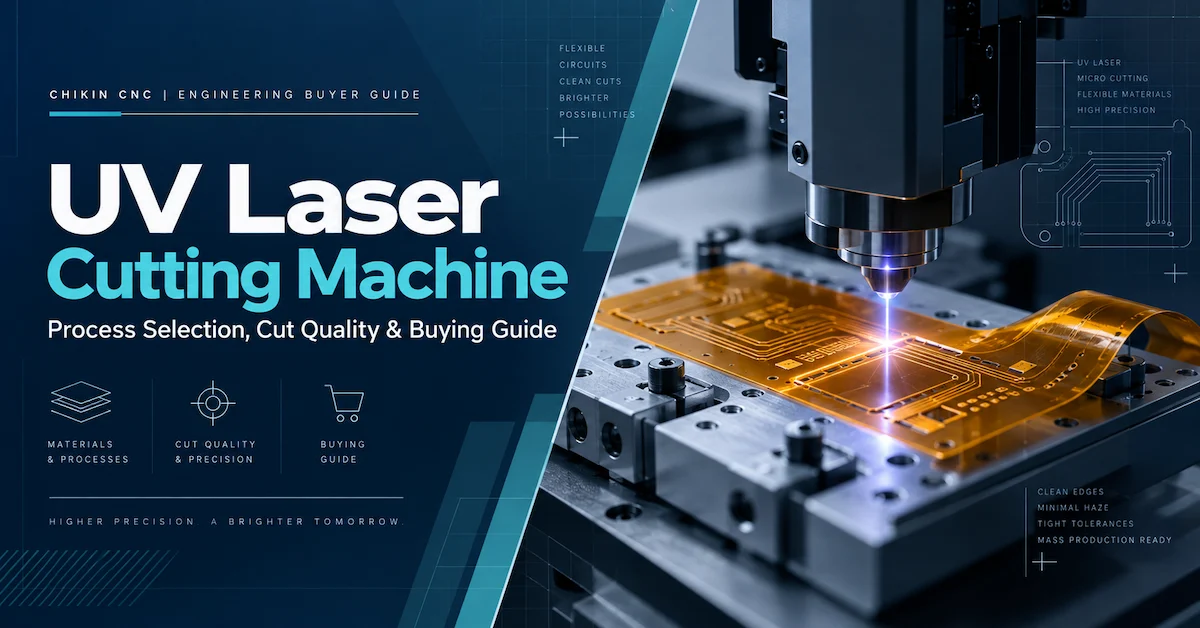
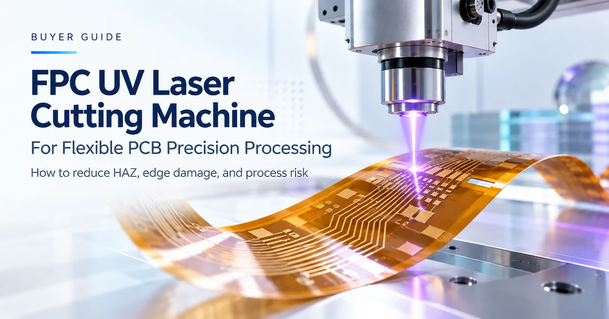
An FPC UV Laser Cutting Machine is a precision processing system that uses ultraviolet laser energy to cut, trim, or separate flexible printed circuits without applying the mechanical cutting force associated with blades, routers, or punching dies.
It is particularly useful when flexible circuit manufacturers need to process thin polyimide substrates, intricate outlines, narrow openings, or delicate multilayer constructions while maintaining controlled edge quality and positional accuracy.
However, selecting the right machine is not simply about finding the highest laser power or the fastest advertised cutting speed.
The most suitable machine is the one that consistently produces acceptable flexible circuits at the required cycle time, with controlled thermal effects, reliable registration, and manageable operating costs.
This distinction matters because flexible circuits behave differently from conventional rigid PCBs.
An FPC panel may contain thin dielectric film, copper conductors, adhesive layers, coverlay, protective coatings, and local reinforcement. Each material responds differently to concentrated laser energy.
A process that produces clean edges on bare polyimide film may behave differently when cutting through a copper-clad or adhesive-containing laminate.
For production managers and equipment engineers, the central question is therefore:
Can the machine process the actual FPC stack-up without unacceptable carbonization, delamination, copper damage, distortion, or loss of dimensional accuracy?
CHIKIN CNC provides dedicated FPC UV Laser Cutting Routing Machines for manufacturers evaluating non-contact flexible circuit processing.
This guide examines the technical and commercial factors that determine whether UV laser cutting is appropriate for your production requirements.
Why Is Flexible PCB Cutting More Difficult Than Rigid PCB Cutting?
Flexible printed circuits are designed to bend, fold, and fit into compact electronic products. Their mechanical flexibility creates several challenges during manufacturing.
Unlike a rigid FR4 board, an unsupported FPC panel may shift, curl, stretch, or wrinkle during processing.
Even small changes in position can affect the relationship between the finished outline and the copper circuitry.
Mechanical Deformation
Conventional cutting processes involve physical contact.
A routing bit removes material through mechanical cutting forces. Punching uses a die and opposing force to separate material. Blade-based cutting introduces local pressure at the cutting line.
These methods can work well for suitable FPC designs, but they may create problems when material is extremely thin or poorly supported.
Potential issues include stretching, wrinkling, edge tearing, deformation, and inconsistent part positioning.
UV laser cutting eliminates the mechanical cutting force at the processing point.
However, the workpiece still needs proper support because the film can move due to vacuum conditions, airflow, thermal effects, or handling.
Complex Circuit Geometry
Many flexible circuits have narrow contours, curved edges, small openings, and irregular shapes.
Examples include:
-
wearable device interconnects
-
camera module circuits
-
display connections
-
flexible sensor circuits
-
medical electronic assemblies
-
compact automotive electronics
-
rigid-flex circuit transitions
Mechanical tools have physical diameter and clearance limitations.
A properly configured UV laser system can follow fine programmed contours without a rotating cutting tool contacting the substrate.
The actual minimum feature size still depends on beam characteristics, motion control, material behavior, and the approved cutting process.
Layered Material Construction
An FPC is not necessarily a single polymer sheet.
A multilayer structure may combine dielectric film, copper, adhesive, and protective materials with different thermal properties.
Heat can affect these layers differently.
An unacceptable cutting process may produce a visually acceptable outline while weakening the laminate near the cut.
For this reason, inspection must consider more than appearance.
Strict Dimensional Requirements
In compact electronics, the outline may sit close to functional circuitry.
A cutting error can reduce conductor clearance, expose copper, or interfere with downstream assembly.
The equipment must therefore maintain alignment between the programmed contour and the actual circuit features.
This is where workholding, calibration, software compensation, and vision alignment become important.
Which FPC Materials Can Be Processed with UV Laser Cutting?
Material compatibility must be evaluated by complete stack-up rather than by the broad term “flexible PCB.”
Different substrate constructions require different process settings and acceptance criteria.
Polyimide-Based FPC
Polyimide is widely used in flexible circuitry because it provides useful thermal, mechanical, and electrical properties.
UV laser systems are commonly evaluated for polyimide cutting because ultraviolet wavelengths can provide effective energy absorption and fine material removal.
Potential applications include exterior contour cutting, fine openings, and flexible circuit separation.
However, a process that works on bare polyimide may need significant adjustment when the material contains copper, adhesive, or additional protective layers.
Copper-Clad Flexible Laminates
Copper introduces another material response.
The laser must remove or pass through the required materials without damaging adjacent conductive features.
Copper reflectivity, thickness, thermal conductivity, and the relationship between the cutting path and conductor pattern can all influence the result.
Buyers should provide copper thickness and conductor-clearance requirements rather than only total board thickness.
Coverlay and Adhesive Layers
Coverlay protects flexible circuitry while allowing selected areas to remain exposed for electrical connection.
Some FPC designs use adhesive-coated coverlay, while others use different protective structures.
Adhesives and polymer layers may respond differently to laser energy.
Improper processing can cause edge residue, discoloration, or local layer separation.
A sample test should therefore include the finished construction, not only the base film.
PET and Other Thin Electronic Films
Some electronic products use PET and other thin polymer films.
A UV processing system may be considered for these materials, but compatibility is not automatic.
Their thermal behavior and process windows can differ substantially from polyimide.
The supplier must verify material suitability rather than assume that a process developed for one polymer will transfer directly to another.
FPC Material Compatibility Checklist
| Material or layer | Typical application | Main processing concern | What buyers should verify |
|---|---|---|---|
| Polyimide film | FPC base substrate | Carbonization and thermal damage | Edge condition and HAZ |
| Copper foil | Conductive circuitry | Conductor damage or exposure | Copper-to-edge clearance |
| Adhesive layers | Flexible laminate construction | Residue and delamination | Bond integrity after cutting |
| Coverlay | Circuit protection | Edge recession and discoloration | Protective coverage |
| PET film | Selected flexible electronics | Melting or deformation | Material-specific process feasibility |
| Rigid-flex transition | Hybrid circuit construction | Layer damage and registration | Cross-sectional quality |
| Stiffeners | Local reinforcement | Thickness and thermal variation | Cutting path and support |
| Surface coatings | Circuit protection | Residue or unwanted removal | Coating integrity |
A supplier's material list is only the starting point. Final approval should be based on the actual production laminate.
For buyers working with several material types, a sample library covering the thinnest, thickest, and most difficult stack-ups is more useful than one demonstration panel.
How Does UV Laser Cutting Work on Flexible Circuits?
UV laser processing uses focused ultraviolet light to deliver energy to a small area of the workpiece.
The absorbed energy removes or modifies material along a programmed path.
For many industrial UV systems, pulsed laser operation allows energy delivery to be controlled through parameters such as pulse frequency, pulse duration, average power, scanning speed, and the number of processing passes.
The actual process depends on the laser source and optical configuration.
Why Wavelength Matters
Material absorption varies with wavelength.
A shorter wavelength can interact differently with polymeric materials than a longer infrared wavelength.
This can make ultraviolet laser processing advantageous for selected thin electronic materials and fine features.
It does not mean every UV laser produces a completely heat-free cut.
Laser processing still involves energy deposition.
Depending on the material and process conditions, some of that energy can create thermal effects.
Why Multiple Passes May Be Necessary
Some materials cannot be processed to the required quality in a single pass.
A multi-pass approach divides material removal into controlled stages.
Potential advantages include improved depth control and reduced excessive energy delivery during any one pass.
However, additional passes increase processing time.
They may also produce cumulative thermal effects if the process is poorly controlled.
The correct number of passes should be established through testing.
Why Laser Power Alone Is Insufficient
Two UV laser systems with similar average power may produce different results.
Relevant variables include:
-
wavelength
-
pulse duration
-
pulse repetition frequency
-
pulse energy
-
beam quality
-
focus diameter
-
working distance
-
scanning or stage speed
-
power stability
-
optical condition
For precision flexible PCB processing, these parameters must be considered together.
A higher-power machine does not automatically deliver better edge quality.
A lower-power machine does not automatically produce a smaller HAZ.
The only reliable comparison is a controlled process test on equivalent materials under equivalent acceptance requirements.
What Applications Benefit Most from FPC UV Laser Cutting?
An FPC UV laser system can support several flexible electronics manufacturing operations, depending on its configured process capability.
Flexible Circuit Outline Cutting
Contour cutting separates the finished circuit shape from the parent sheet or panel.
This is especially useful for irregular FPC profiles with narrow curves, small tabs, or geometry that changes frequently between product designs.
FPC Depaneling
Depaneling separates individual flexible circuits from a larger production panel.
Laser processing can reduce the mechanical loading associated with conventional separation methods.
The advantage is most relevant when the circuit contains delicate features, narrow connecting sections, or regions that are easily distorted.
Precision Openings and Windows
Selected applications require small openings, slots, or cutouts.
Examples include mechanical positioning features, assembly openings, and access areas.
The required geometry should be reviewed against the laser spot size, achievable kerf, substrate thickness, and registration capability.
Prototype Development and NPI
New Product Introduction frequently involves changing dimensions, outlines, and design revisions.
A programmable laser path can reduce dependence on dedicated mechanical dies for suitable materials.
This is particularly attractive when product designs change before mass production.
Rigid-Flex Circuit Processing
Rigid-flex boards combine flexible sections with rigid areas.
A UV laser may be evaluated for selected flexible-region processing tasks.
However, rigid sections and transitions can have different material compositions and thicknesses.
The supplier should not assume that the same recipe will process every part of the assembly.
High-Mix, Low-to-Medium-Volume Manufacturing
Factories producing many different FPC designs may benefit from programmable cutting and simplified product changeovers.
The actual benefit depends on setup time, fixture requirements, program management, and acceptable cycle time.
For a detailed product overview, review CHIKIN's FPC UV Laser Cutting Routing Machine for Precise Flexible Circuit Processing.
Which Buyers Should Consider an FPC UV Laser Cutting Machine?
UV laser processing is not equally valuable for every electronics manufacturer.
The business case depends on the application.
| Buyer type | Main production challenge | Why UV laser processing may help |
|---|---|---|
| Flexible PCB factory | Distortion and inconsistent contours | Non-contact programmable cutting |
| Rigid-flex manufacturer | Sensitive transition areas | Controlled processing of selected flexible regions |
| Wearable electronics supplier | Small, complex circuit geometry | Fine-feature capability |
| Medical electronics supplier | High reliability and traceability requirements | Controlled, documented process qualification |
| Consumer electronics manufacturer | Frequent design changes | Software-based contour changes |
| FPC prototyping laboratory | Small batches and changing designs | Reduced dependence on dedicated dies |
| High-mix contract manufacturer | Product changeovers | Programmable processing recipes |
A factory producing relatively simple FPC shapes in very high quantities may still find conventional die cutting economical.
A plant cutting thicker rigid PCBs may be better served by mechanical routing.
The selection should reflect the full manufacturing economics, not just the appeal of laser technology.
What Technical Specifications Matter When Choosing an FPC UV Laser Cutting Machine?
Buyers should request a complete application-specific technical specification.
The public description of CHIKIN's FPC UV equipment identifies the machine's general application and enclosed industrial structure, but final laser and automation parameters should be verified for the specific configuration quoted.
The following factors are particularly important.
Laser Source and Pulse Characteristics
Ask for the exact laser type, wavelength, average power, pulse characteristics, and operating range.
The goal is not simply to maximize energy.
The goal is to establish a stable processing window for the material stack.
Effective Working Area
The machine must accommodate the full production panel, not only the final individual circuit.
Check whether the published work area includes space for fixtures, alignment references, and safe process margins.
Also ask whether the entire stated area maintains the required processing performance.
Motion and Scan Accuracy
A UV processing system may use a motion stage, galvanometer scanning, or another optical-motion architecture.
Each approach has different performance characteristics.
Buyers should clarify how cutting accuracy is measured across the usable working field.
CCD or Vision Alignment
Vision alignment may be important when the cutting path must follow actual circuit positions.
However, a displayed camera or monitor does not establish the full capability of a vision-registration system.
Confirm whether the quoted configuration includes fiducial recognition, automatic correction, and the accuracy required for your product.
Workholding System
Thin FPC panels require controlled support.
Depending on the material and equipment, options may include vacuum holding, carrier plates, alignment pins, or dedicated fixtures.
The supplier should show how the workpiece remains stable throughout the complete process.
Cooling and Extraction
Confirm the cooling arrangement, fume extraction requirement, filter configuration, and maintenance expectations.
These affect both production quality and factory integration.
Machine Specification Checklist
| Specification | Information to request | Acceptance focus |
|---|---|---|
| Laser source | Type, wavelength, pulse specifications | Material compatibility |
| Processing capacity | Laser and motion capability | Approved process window |
| Working area | Effective X/Y dimensions | Maximum production panel |
| Z/focus control | Focus method and allowable variation | Consistent cutting |
| Positioning system | Motion/scanning architecture | Finished-part accuracy |
| Vision system | CCD/fiducial functions, if configured | Cut-to-pattern registration |
| Workholding | Vacuum, carrier, fixtures | Flatness and stability |
| Software | Supported files and recipe functions | Production changeover |
| Extraction | Fume removal and filtration requirements | Clean processing environment |
| Cooling | Cooling system and utility requirements | Stable operation |
| Safety | Enclosure, interlocks, emergency controls | Safe integration |
| Automation | Manual or integrated handling options | Production capacity |
Specifications should describe the complete delivered machine, not optional features that are absent from the quotation.
How Important Is CCD Alignment for Flexible PCB Laser Cutting?
Positioning accuracy is one of the most misunderstood equipment specifications.
A machine may have excellent mechanical repeatability yet still produce unacceptable parts if the flexible panel moves or the cutting program is misaligned with the actual circuitry.
Axis Accuracy Is Not Finished-Part Accuracy
Equipment specifications often use the word “accuracy” to describe different measurements.
These may include:
-
axis positioning accuracy
-
motion repeatability
-
camera recognition repeatability
-
fiducial registration accuracy
-
cut-to-pattern accuracy
-
finished-part dimensional accuracy
These values cannot be used interchangeably.
For an FPC manufacturer, the most relevant acceptance measurement is often the relationship between the finished cut and the electrical circuit features.
Why Fiducials Matter
Flexible panels can undergo dimensional changes during previous manufacturing stages.
If the cutting system uses only a nominal programmed origin, variations in panel placement or dimensions may create errors.
A properly configured vision-registration system can use fiducial references to identify the panel position and apply the permitted correction.
Depending on the system, this may include translation, rotation, or more advanced compensation.
Registration Must Be Tested Across the Panel
One accurate reference point does not guarantee that the entire panel is correctly aligned.
Large panels may show localized distortion.
For demanding applications, buyers should evaluate multiple points across the usable work area.
The supplier should document both its registration strategy and the residual cutting error after correction.
If your process requires tight copper-to-edge clearance, include that measurement in the sample acceptance plan.
How Should Thin FPC Panels Be Held During Laser Cutting?
Workholding is a major factor in process repeatability.
A laser eliminates tool contact, but it does not eliminate the need to secure the material.
A thin circuit panel may lift, curl, move, or distort under environmental and process conditions.
Vacuum Fixtures
Vacuum can provide distributed support for suitable thin panels.
However, excessive or uneven suction may deform delicate material or affect areas with openings.
The fixture must be designed around the actual panel geometry.
Carrier Plates
A carrier can help support material through loading, processing, and unloading.
Carrier selection should account for flatness, thermal behavior, contamination, and how the laser interacts with the support beneath the cut.
Alignment Pins and Locating Features
Mechanical locating features can improve loading consistency.
However, they cannot always compensate for dimensional variation within the flexible sheet.
For tight registration, mechanical location may need to be combined with optical alignment.
Part Retention After Separation
A detail often overlooked during procurement is what happens when the final connection between the individual circuit and the parent panel is removed.
The finished part may shift, curl, or fall into an unsuitable area.
The process should define how individual circuits remain supported until unloading.
This small detail can significantly affect automation, handling damage, and production yield.
How Can Manufacturers Reduce Heat-Affected Zones in FPC Laser Cutting?
The heat-affected zone, or HAZ, is the region near the cut that experiences thermal influence.
In flexible circuit processing, thermal effects may appear as discoloration, carbonization, local deformation, adhesive changes, or damage to laminated structures.
A non-contact laser cut is not automatically a zero-HAZ process.
The objective is to establish a cutting window in which the required material is removed while adjacent functional structures remain acceptable.
Factors That Influence HAZ
The main variables include laser wavelength, energy delivery, focus, pulse behavior, cutting speed, number of passes, material thickness, and thermal properties.
Excessive energy concentration can increase unwanted thermal effects.
On the other hand, reducing power without considering cutting speed and passes may result in incomplete penetration or excessive dwell time.
This is why single-parameter optimization often fails.
Use a Controlled Process Study
An application engineer should evaluate a reasonable range of settings while holding the material, cut geometry, and inspection method constant.
The goal is to identify a stable operating window rather than the one sample that looks best under a microscope.
A practical study might compare:
-
different approved energy settings
-
cutting speeds
-
pulse settings
-
focus positions
-
pass strategies
-
path sequences
Every trial should record both cutting quality and processing time.
Inspect More Than the Surface
Surface photographs can reveal discoloration, roughness, or debris, but they may not show all subsurface effects.
When the application is critical, cross-sectional examination or additional electrical and mechanical testing may be justified.
For high-reliability flexible circuits, acceptance requirements should follow the customer's approved product specification and applicable standards.
IPC-6013 is a relevant performance and qualification specification for flexible and rigid-flex printed boards. It is not, by itself, a certification of an individual laser-cutting machine.
Common FPC UV Laser Cutting Defects and Their Possible Causes
Understanding process defects is essential when evaluating machine capability.
A supplier should be able to explain how it investigates these problems.
| Defect | Possible contributing factors | Recommended investigation |
|---|---|---|
| Brown or black edge discoloration | Excessive local thermal influence | Review energy, speed, focus, passes, and material |
| Carbonized edge | Thermal degradation of polymer | Inspect process window and cross-section |
| Incomplete cutting | Insufficient effective material removal | Check focus, energy, passes, and stack-up |
| Edge residue | Material decomposition or extraction issues | Examine material response and fume removal |
| Delamination | Local heat or existing bond weakness | Examine layer construction and process conditions |
| Exposed or damaged copper | Incorrect path, registration, or thermal interaction | Check CAM data, fiducials, and conductor clearance |
| Dimensional variation | Material movement, calibration, or thermal distortion | Verify fixtures and registration |
| Inconsistent notch | Focus variation, beam/process instability | Inspect optics, flatness, and process parameters |
| Part movement | Insufficient support after separation | Review carrier and retention design |
| Excessive cycle time | Inefficient path, too many passes, handling delays | Review complete process sequence |
These are diagnostic starting points, not guaranteed causes.
For example, edge discoloration can originate from material behavior rather than a single incorrect laser-power setting.
A reliable troubleshooting process should compare a known-good sample with the defective result, then isolate the most likely contributing variables.
The distinction is commercially important.
A machine that produces one attractive sample but cannot maintain quality across normal material variation may create more production cost than it saves.
What Is a Good FPC Laser Cutting Workflow?
A practical production process should connect engineering data, machine setup, cutting, inspection, and traceability.
Stage 1: Engineering Data Preparation
The production team prepares the approved contour and panel information.
This may originate from Gerber, DXF, CAD, or other manufacturing data, depending on the equipment and software workflow.
Supported file formats should be confirmed before purchasing.
The cutting program must identify the approved path relative to circuit features and any required clearance.
Stage 2: Material Identification
Operators select the correct material and process recipe.
A recipe developed for one polyimide-copper construction should not automatically be approved for a different adhesive or copper thickness.
Stage 3: Workpiece Loading
The panel is placed into the approved fixture.
The setup should prevent uncontrolled movement without damaging the flexible material.
Stage 4: Registration and Focus Verification
If the configuration includes vision alignment, the machine locates the selected references and applies approved corrections.
Focus and material height should be checked as required by the process.
Stage 5: Laser Processing
The equipment executes the programmed path using the approved process parameters.
The cutting strategy should account for contour order, part retention, thermal effects, and completed-part handling.
Stage 6: Unloading and Inspection
The operator or automation system removes the parts.
Inspection verifies critical dimensions, edge condition, and any product-specific electrical or mechanical criteria.
Stage 7: Process Data and Traceability
For controlled manufacturing environments, records may include job identification, recipe revision, sample results, inspection findings, and machine alarms.
The exact data-logging capability should be confirmed with the machine supplier.
FPC UV Laser Cutting vs Die Cutting vs Mechanical Routing
Laser processing should be selected only when it provides a practical advantage for the specific job.
| Evaluation factor | UV laser cutting | Die cutting | Mechanical routing |
|---|---|---|---|
| Mechanical contact at cut | No cutting-tool contact | Yes | Yes |
| Design flexibility | High for supported geometry | Limited by dedicated tooling | High within tool-access limits |
| Fine contours | Potentially strong | Depends on die design | Limited by cutter diameter and access |
| Tool wear | No mechanical cutting edge | Die wear | Cutter wear |
| Thermal influence | Must be controlled | No laser-induced HAZ | No laser-induced HAZ |
| Changeover | Recipe and fixture dependent | Tooling dependent | Program and fixture dependent |
| Very high stable volume | Depends on cycle time | Often competitive | Depends on geometry |
| Material distortion risk | Primarily handling and thermal effects | Mechanical loading | Mechanical loading |
| Primary cost concern | Laser, optics, extraction, cycle time | Dies and maintenance | Tools, dust, cycle time |
When UV Laser Cutting Is a Strong Candidate
Consider UV laser processing when the part is thin, delicate, geometrically complex, or subject to frequent design changes.
It is also attractive when mechanical separation has produced unacceptable deformation or localized damage.
When Die Cutting May Be Better
For a stable design produced in large quantities, a validated die-cutting process may deliver a shorter cycle at an acceptable cost per part.
Die cost, maintenance, material handling, and quality requirements still need evaluation.
When Mechanical Routing May Be Better
For rigid PCB applications or geometries that can be processed efficiently with a suitable cutter, routing may offer a simpler economic solution.
CHIKIN provides a broader PCB Drilling and Routing Machine range for buyers comparing mechanical alternatives.
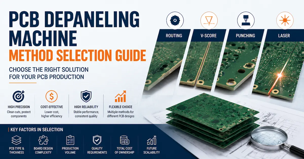
For a wider discussion of routing, V-CUT, punching, and laser, see the PCB Depaneling Machine Selection Guide.
How Should Manufacturers Validate an FPC UV Laser Cutting Machine Before Purchase?
A meaningful sample test should reproduce the production challenge.
Sending a random piece of material and asking the supplier to demonstrate laser cutting is not enough.
Select Representative Samples
A useful validation package may include the thinnest and thickest approved constructions, the most complex contour, the narrowest relevant clearance, and any material known to be difficult.
When multiple suppliers provide samples, each should work from the same drawing revision and acceptance specification.
Establish Pass/Fail Criteria First
Before cutting, agree on the measured requirements.
Examples include:
-
finished outline dimensions
-
maximum permitted edge discoloration
-
acceptable HAZ condition
-
minimum conductor-to-edge clearance
-
absence of unacceptable delamination
-
cut completeness
-
registration accuracy
-
repeatability
-
cycle-time target
Numerical limits should come from the customer's design and qualification requirements.
They should not be invented from a machine brochure.
Use Multiple Consecutive Samples
A first-piece demonstration shows feasibility.
A repeated production run provides evidence about stability.
Ask the supplier to demonstrate the process across a defined sample quantity and, where appropriate, multiple material lots.
Inspect Critical Features
Use suitable calibrated methods for dimensional and visual inspection.
For critical circuits, additional inspection may be necessary to understand laminate integrity or downstream electrical behavior.
Document the Approved Process
A successful sample should be connected to a documented parameter set.
Without that record, the factory may struggle to reproduce the same result during installation.
Sample Acceptance Checklist
| Acceptance item | Required evidence | Responsibility |
|---|---|---|
| Material identification | Actual stack-up and lot | Buyer |
| Cut-path approval | Released drawing and revision | Buyer |
| Dimensional accuracy | Measurement report | Supplier / buyer |
| Cut-to-pattern registration | Fiducial-based measurement | Supplier / buyer |
| Edge quality | Calibrated inspection images | Supplier / buyer |
| Thermal effect | Agreed inspection method | Supplier / buyer |
| Laminate integrity | Additional testing if required | Buyer / qualified laboratory |
| Repeatability | Consecutive sample results | Supplier |
| Cycle time | Recorded complete cycle | Supplier |
| Recipe documentation | Approved parameter record | Supplier |
This approach reduces the risk of comparing machines based on unrelated demonstration conditions.
How Do You Calculate Real FPC Laser Cutting Production Capacity?
One of the biggest mistakes in equipment purchasing is comparing maximum laser scanning speed with factory output requirements.
Scanning speed is only one part of the process.
Finished-part output also depends on loading, alignment, focusing, processing passes, unloading, inspection, and changeover.
A practical calculation is:
Gross circuits per hour = 3,600 × circuits per panel ÷ complete panel cycle time in seconds
This is a planning equation, not a guarantee of actual machine output.
For production forecasting, the calculation should then account for equipment availability and conforming-product yield.
Estimated good circuits per hour = gross circuits per hour × availability factor × quality yield
If performance is reported through a formal Overall Equipment Effectiveness methodology, use one consistent definition and avoid subtracting the same loss twice.
Why Cut Length Matters
Two FPC panels of equal size may have very different processing times.
One may contain simple exterior contours.
The other may have many narrow openings and complex internal features.
The number of cuts, total cutting path, process passes, and movement sequence can significantly affect output.
Why Yield Matters
High nominal speed has limited value if the resulting edge condition creates unacceptable scrap or additional inspection.
For investment evaluation, calculate cost per conforming circuit rather than cost per cutting cycle.
Why Changeover Matters
High-mix manufacturers should also measure recipe loading, fixture replacement, first-piece verification, and operator adjustment time.
A machine with a slightly slower cutting cycle may be more productive over a week if it handles product changeovers more efficiently.
For buyers considering high-volume processing, CHIKIN's Laser Cutting Machine product range provides an overview of different laser-processing directions that can be reviewed against production capacity requirements.
What Factory Conditions Are Required for UV Laser Cutting?
Machine integration should be discussed during the purchasing stage.
The installation plan may involve electrical supply, cooling, extraction, material handling, and safety systems.
Electrical Requirements
Confirm voltage, frequency, phase, connected load, grounding, and electrical protection for the actual supplied model.
Do not assume requirements based on another laser-processing machine.
Cooling Requirements
Laser sources and optical systems may use different cooling arrangements.
Confirm the specific system, its environmental requirements, and any maintenance responsibilities.
Fume Extraction
Laser processing can generate fumes and particles from polymer, adhesive, copper-bearing, or coated materials.
An enclosed cabinet does not, by itself, establish that extraction is sufficient.
Ask the supplier to specify required airflow, connection arrangements, monitoring, and filter maintenance where applicable.
Environmental Conditions
Temperature, humidity, cleanliness, vibration, and floor stability can affect manufacturing consistency.
The supplier should define the applicable installation conditions rather than simply state that the machine is suitable for a factory environment.
Safety
Industrial laser equipment requires appropriate protective measures.
ISO 11553-1:2020 addresses laser radiation hazards and safety requirements for laser-processing machines.
IEC 60825-1 is relevant to laser-product classification and safety considerations.
Buyers should request machine-specific safety documentation, including information about:
-
protective enclosure
-
access interlocks
-
emergency stop
-
viewing arrangements
-
maintenance conditions
-
laser classification
-
hazard control
-
operator instructions
The existence of a safety standard should not be confused with proof that a particular machine is certified to it.
How Should FPC Cutting Quality Be Inspected?
A reliable quality-control plan should separate three different questions.
Did the machine cut the correct geometry?
Did it produce an acceptable physical edge?
Did the circuit retain the required electrical and mechanical performance?
These questions require different evidence.
Dimensional Inspection
Measure the finished outline and critical features using an inspection method appropriate to the tolerance.
For tight applications, include measurement uncertainty and equipment calibration.
Edge Inspection
Inspect for discoloration, carbonization, roughness, incomplete cutting, and residue.
Critical defects may require magnification or sectioning beyond standard visual inspection.
Electrical Integrity
Depending on the circuit design, electrical testing may be necessary to confirm that conductive features remain functional.
Mechanical Integrity
Flexible circuits may experience repeated bending in use.
When the cut is near a critical flex region, product-specific mechanical qualification may be necessary.
The appropriate qualification plan depends on the application and customer requirements.
Applicable Standards
IPC-6013 provides qualification and performance requirements for flexible and rigid-flex printed boards.
Buyers should identify the required document revision, product classification, and customer-specific acceptance criteria before agreeing on a process.
A successful machine demonstration does not replace finished-board qualification.
What Should Be Included in the Factory Acceptance Test?
The FAT should demonstrate that the delivered equipment configuration can meet the agreed requirements before shipment.
It should not be reduced to switching on the machine and showing a sample.
Machine Configuration Review
Verify the supplied laser source, working area, software, optics, controls, workholding, extraction interfaces, cooling arrangements, and included options against the purchase specification.
Process Verification
Run the approved material and part geometry.
Record cut quality, dimensional accuracy, registration, thermal effects, and complete cycle time.
Repeatability Verification
Evaluate an agreed number of consecutive parts or panels.
Define how deviations are handled.
Safety Verification
Review relevant protective functions, interlocks, emergency controls, and required documentation.
Documentation Review
Confirm operating instructions, maintenance guidance, spare-parts information, approved process recipes, and training scope.
FAT Acceptance Matrix
| FAT item | Acceptance basis |
|---|---|
| Machine configuration | Agreed technical specification |
| Material compatibility | Approved production stack-up |
| Program execution | Released cut-path data |
| Finished dimensions | Drawing tolerances |
| Edge condition | Approved visual/process limits |
| Registration | Cut-to-pattern requirement |
| Thermal influence | Customer acceptance specification |
| Production cycle | Agreed timing method |
| Repeatability | Defined sample quantity and limits |
| Safety functions | Applicable machine requirements |
| Documentation | Contract deliverables |
| Training | Agreed training scope |
Keep the approved FAT report as part of the project record.
It can provide a useful reference when comparing machine performance before and after installation.
What Determines FPC UV Laser Cutting Machine Price?
The purchase price depends on the actual specification and integration scope.
Important cost factors may include:
-
UV laser source
-
pulse and optical configuration
-
processing field
-
motion architecture
-
vision alignment
-
software capability
-
fixture design
-
extraction equipment
-
cooling
-
automation
-
material handling
-
factory integration
-
installation
-
training
-
spare parts
A quotation that includes only the machine cabinet may not represent the full cost of putting the process into production.
Initial Price vs Total Cost
The relevant commercial question is not simply:
“How much does the machine cost?”
It is:
“What does it cost to produce one conforming flexible circuit over the expected operating life?”
A useful total-cost model includes machine investment, tooling or fixtures, energy, cooling, extraction, maintenance, labor, consumables, scrap, rework, and downtime.
The buyer should also consider future product changes.
For a high-mix factory, lower fixture and tooling expenditure may justify a higher equipment investment.
For a stable high-volume product, a validated mechanical process may still offer better economics.
Ask for a Comparable Quote
When requesting quotations from several suppliers, use the same material stack, drawings, acceptance criteria, production target, and integration scope.
Otherwise, lower pricing may simply reflect missing equipment or services.
What Customization Options Should FPC Manufacturers Discuss?
A standard machine configuration may be sufficient for some applications.
Other factories require specialized integration.
Possible topics include working area, fixtures, vision registration, automated handling, software workflow, extraction, and MES connectivity.
These should be treated as configuration requirements to confirm rather than standard features automatically included with every machine.
Custom Workholding
Thin or irregular circuits may require dedicated carriers or fixtures.
The fixture should support stable positioning and controlled removal of finished parts.
Vision Alignment
When cut-to-pattern accuracy is critical, request the appropriate vision registration method and a corresponding acceptance test.
Loading and Unloading
Automation can reduce manual handling, but it must also preserve the flexibility of the material.
Discuss how panels and finished circuits are supported, transported, and separated.
Software and Production Data
High-mix manufacturers may need recipe revision control, approved cutting programs, user permissions, traceability data, and integration with factory systems.
Confirm available interfaces and development scope before ordering.
CHIKIN CNC's Service Advantages page provides additional company service information. Buyers should confirm the specific customization, commissioning, and support terms in their project quotation.
How to Evaluate an FPC UV Laser Cutting Machine Manufacturer
Supplier capability influences the complete lifecycle of the equipment.
A professional evaluation should consider more than machine appearance.
Application Knowledge
Can the supplier explain the interaction between ultraviolet energy and your FPC stack-up?
Can the engineering team identify likely risks involving adhesive, copper, coverlay, material distortion, and cut quality?
Process Validation
Can the supplier arrange a meaningful sample test using the correct material and acceptance criteria?
Can it provide evidence of repeatability?
Equipment Engineering
Can the supplier describe the motion platform, control software, optics, fixtures, extraction, and maintenance requirements?
Quality and Documentation
Can it supply a complete technical specification, FAT plan, operating instructions, and maintenance information?
After-Sales Support
Will the project include the required installation guidance, training, troubleshooting arrangements, and spare-parts support?
These are particularly important for overseas buyers.
Supplier Evaluation Scorecard
| Supplier factor | What to ask |
|---|---|
| Application expertise | Has the supplier evaluated similar FPC stack-ups? |
| Sample validation | Can it demonstrate the approved cut quality? |
| Accuracy evidence | Is finished-part accuracy measured? |
| Process stability | Are repeated sample results available? |
| Fixture engineering | How are flexible materials supported? |
| Documentation | Are specifications and FAT criteria complete? |
| Service | What support is included after delivery? |
| Integration | Can the system fit the actual production workflow? |
CHIKIN CNC's About Us page provides company background, while its dedicated FPC product pages describe the intended flexible-circuit processing applications.
What Information Should You Send for an FPC UV Laser Cutting Machine Quotation?
A useful RFQ starts with the application.
The more accurately the buyer describes the job, the easier it becomes to recommend a relevant machine configuration.
Recommended RFQ Information
| Category | Information required |
|---|---|
| Application | FPC outline, depaneling, windows, or other process |
| Material | Polyimide, PET, copper-clad laminate, rigid-flex, etc. |
| Stack-up | Film, copper, adhesive, coverlay, coatings |
| Thickness | Minimum, maximum, and typical |
| Panel size | Maximum length and width |
| Finished-part size | Dimensions and geometry |
| Drawing files | Gerber, DXF, CAD, or relevant approved format |
| Quality | Tolerance, HAZ, edge condition, registration |
| Production | Parts per shift, panel count, product mix |
| Handling | Manual, semi-automatic, or integrated loading |
| Utilities | Electrical, cooling, extraction requirements |
| Installation | Country, site conditions, commissioning needs |
| Acceptance | Sample testing and FAT criteria |
For a project involving multiple FPC constructions, include representative samples of each important material combination.
Also explain which part presents the greatest production difficulty.
An engineering team can often make a more useful recommendation when it understands the failure that the current process cannot solve.
Request an Application-Based Recommendation
Instead of asking only for a machine price, request:
A machine configuration recommendation, sample-cutting evaluation, required utilities, estimated cycle time under approved conditions, FAT proposal, and itemized quotation.
CHIKIN CNC offers an FPC UV Laser Cutting Routing Machine for flexible circuit processing applications.
For application review and purchasing inquiries, use the CHIKIN CNC Contact Page.
Frequently Asked Questions About FPC UV Laser Cutting Machines
1. What is an FPC UV Laser Cutting Machine used for?
An FPC UV Laser Cutting Machine is used for precision processing of suitable flexible printed circuits, including outline cutting, depaneling, contour trimming, and selected openings.
Its main advantage is non-contact processing.
This makes it attractive for thin or delicate materials that may deform under mechanical cutting forces.
However, actual compatibility depends on the laser configuration, substrate structure, cutting geometry, and required edge quality.
2. Why is UV laser cutting suitable for polyimide flexible circuits?
Ultraviolet laser processing can provide favorable energy absorption and fine material removal for selected polyimide constructions.
This can support narrow contours and localized processing without a mechanical cutting tool contacting the film.
The final result depends on pulse behavior, laser energy, focus, cutting speed, and the complete laminate stack.
A UV laser should not automatically be described as producing heat-free cuts.
3. Can UV laser cutting damage copper traces?
Yes, if the process or cutting path is unsuitable.
Copper damage may result from incorrect registration, insufficient clearance, unsuitable energy settings, or other process conditions.
For applications with tight conductor-to-edge spacing, the buyer should require cut-to-pattern accuracy measurements and inspection of representative samples.
4. Does an FPC laser cutting machine eliminate the heat-affected zone?
No.
Laser processing avoids mechanical cutting forces, but thermal effects may still occur.
The goal is to control those effects within the requirements of the material and finished circuit.
HAZ should be evaluated through an agreed inspection method using the actual production stack-up.
5. Is UV laser cutting better than die cutting for FPC?
It depends on product geometry, volume, material, and cost.
UV laser processing may be advantageous for complex contours, frequent design changes, and sensitive flexible materials.
Die cutting may remain economical for stable, high-volume products when the tooling cost and mechanical effects are acceptable.
A fair comparison should include cycle time, tooling, scrap, maintenance, and changeover.
6. How accurate is an FPC UV Laser Cutting Machine?
Accuracy depends on the machine architecture, calibration, vision system, material stability, fixture, and process conditions.
A quoted axis repeatability value does not necessarily equal finished-part cutting accuracy.
Buyers should request measured cut-to-pattern and finished-dimension results from samples representing their actual production requirements.
7. Can one UV laser cutting system process different FPC thicknesses?
Potentially, but different thicknesses and stack-ups may require different processing parameters.
Changes in film, copper, adhesive, coverlay, or reinforcement can affect absorption, thermal behavior, and the number of cutting passes.
Compatibility should be established for each important material construction.
8. What affects the price of an FPC UV laser cutting system?
Price is influenced by the laser source, optics, working area, motion system, vision alignment, fixtures, extraction, cooling, software, automation, and service scope.
A lower machine price does not necessarily mean a lower cost per conforming part.
The most useful comparison combines the full quotation with sample quality, realistic throughput, maintenance, and expected operating costs.
9. What should I check before accepting an FPC UV laser cutting machine?
The FAT should verify the delivered machine configuration, approved sample performance, dimensions, registration, edge quality, thermal effects, cycle time, repeatability, safety functions, documentation, and included accessories.
Acceptance limits should be agreed before testing.
The supplier should demonstrate the process using representative production materials rather than an unrelated sample.
10. How do I choose a reliable FPC UV Laser Cutting Machine supplier?
Look for a supplier that can understand your circuit construction, explain the laser process, arrange application-specific sample tests, document repeatability, and provide a clear equipment quotation.
Evaluate fixture engineering, software, utilities, installation, training, and maintenance alongside cutting performance.
For a flexible PCB processing project, review CHIKIN CNC's FPC UV Laser Cutting Routing Machine and submit the actual material and drawings for technical evaluation.
Conclusion
An FPC UV Laser Cutting Machine should be selected around the actual flexible circuit material, cut geometry, edge-quality requirements, registration tolerance, and production volume—not laser power alone.
For FPC manufacturers, the most important purchasing decisions involve material compatibility, HAZ control, copper protection, workholding, repeatable cutting quality, and realistic production capacity. A successful sample test and clearly defined FAT provide stronger purchasing evidence than generic performance claims.
CHIKIN CNC offers dedicated flexible circuit laser-processing equipment for manufacturers evaluating precision non-contact cutting. Explore the FPC UV Laser Cutting Machine and contact CHIKIN CNC with your material stack-up, drawings, quality requirements, and production targets to discuss a suitable configuration and quotation.