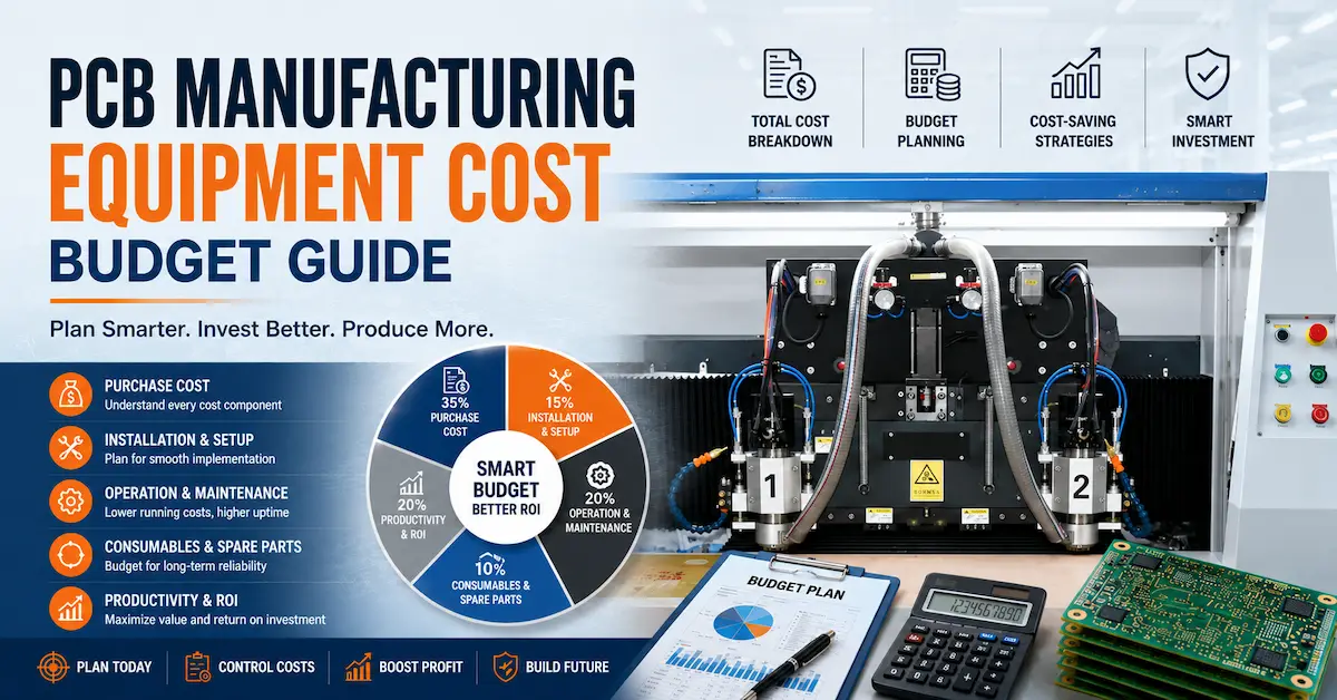




An Auto PCB V Cut Machine should be selected according to the PCB panel design, required operation, cutter arrangement, acceptable board stress, and production volume—not simply the number of cutters listed in a product name.
For rigid PCB manufacturers, automatic V-cut processing can support consistent panel preparation or separation when the board geometry and tooling are suitable. However, a machine designed to create V-shaped grooves is not necessarily the same as equipment that separates boards along grooves already formed during fabrication. Buyers must establish that distinction before comparing quotations.
Four-cutter, six-cutter, and eight-cutter configurations may offer different production possibilities, but additional cutters do not automatically deliver proportionally higher throughput. Panel layout, actual tool engagement, loading time, changeover, maintenance, and acceptable-board yield determine the final result.
This article explains how to evaluate an automatic PCB V-cut machine from an engineering and purchasing perspective. It is intended for PCB factory owners, production managers, process engineers, contract electronics manufacturers, and overseas equipment buyers who need a repeatable process rather than an impressive specification sheet.
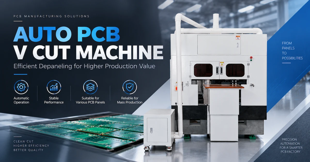
1. What Is an Auto PCB V Cut Machine?
An Auto PCB V Cut Machine is industrial equipment used for controlled processing of PCB panels along specified V-shaped cutting or separation paths. Depending on the machine design, it may create V-grooves in a rigid PCB panel, separate boards along existing V-scores, or support a related automated panel-processing operation.
The process must be identified precisely because two different manufacturing stages are often described using similar commercial terms.
V-scoring: Creating the groove
During PCB fabrication, a V-scoring machine removes material along predetermined straight lines, typically using angled cutting tools.
In a conventional double-sided V-score process, material is removed from the upper and lower surfaces while a controlled thickness of material remains between the grooves.
This remaining material is commonly called the residual web.
Its function is important: the panel must remain sufficiently stable during handling and assembly while still allowing the individual boards to be separated at the appropriate production stage.
If the groove is too shallow, the later separation operation may require excessive force. If the groove is too deep, the panel may become fragile during transportation, solder-paste printing, component placement, or other handling operations.
The correct residual web is therefore a manufacturing specification, not simply a machine setting.
Depaneling: Separating previously scored boards
A PCB depaneling machine performs a different operation.
It separates individual circuit boards from a panel after the V-score has already been produced. Depending on the equipment, this may involve a rolling blade, controlled shearing action, or another guided separation mechanism.
The objective is not to manufacture the original score geometry. It is to divide the panel while controlling board deflection, edge damage, and mechanical loads transferred to nearby components.
For an assembled PCB, these loads can be particularly important because excessive bending may affect solder joints, ceramic capacitors, or other stress-sensitive features near the separation line.
Why this distinction matters when buying equipment
Some suppliers use terms such as PCB V-cut machine, PCB V-scoring machine, PCB V-grooving machine, and PCB separator across similar product listings.
These names alone do not establish what the equipment physically does.
Before purchasing, ask the manufacturer to identify:
-
Whether the machine creates a new groove or separates an existing one.
-
Whether processing occurs before or after component assembly.
-
Whether the machine cuts from one surface or both surfaces.
-
Whether multiple cutters operate simultaneously or sequentially.
-
Whether the machine supports finished, populated PCB assemblies.
-
Whether the quoted configuration includes the required feeding, positioning, and extraction systems.
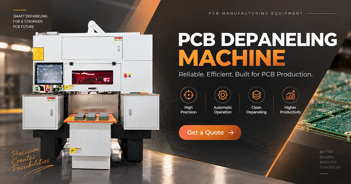
CHIKIN CNC offers equipment under both V-cut and PCB separation terminology. Buyers can review its PCB V-cut and depaneling equipment options and request confirmation of the intended operating mechanism for each model.
Practical recommendation: Ask for an operating video showing the actual cutter-to-board interaction, not only the machine exterior. A sample demonstration with your own panel is more useful than a generic product photograph.
2. When Is Automatic PCB V-Cut Processing the Right Choice?
Automatic V-cut equipment is most relevant when PCB panel geometry permits consistent, repeatable processing along defined straight lines.
Rigid FR4 panels with repeated rectangular board layouts are common candidates. However, board material alone does not determine suitability. The panel drawing, processing stage, score geometry, and final assembly requirements must also be reviewed.
| PCB production requirement | V-cut suitability | Main consideration |
|---|---|---|
| Repeated rectangular rigid PCB panels | Often suitable | Straight score lines and repeatable positioning |
| Large batches of identical panel designs | Potentially advantageous | Changeover frequency and effective cycle time |
| Multilayer rigid FR4 panels | Depends on construction | Board thickness, residual web and internal copper clearance |
| Mixed PCB designs with frequent changeovers | Requires evaluation | Setup time may reduce automation benefits |
| Irregular or curved board outlines | Often unsuitable for conventional straight-line scoring | CNC routing or laser cutting may be more appropriate |
| Flexible PCB panels | Generally not the preferred V-scoring application | Flexible materials require different separation behavior |
| Populated boards with components close to the score | Requires special caution | Mechanical strain during separation |
| Metal-core PCB panels | Requires specific verification | Material, blade, groove and process compatibility |
High-volume rigid PCB manufacturing
For factories producing repeated rigid PCB panel formats, automation can help standardize the relationship between panel positioning, cutting tools, operator actions, and inspection requirements.
A factory manufacturing the same panel throughout several production shifts may benefit from a stable, repeatable setup.
The value comes from reducing process variation and unnecessary handling—not merely increasing machine speed.
If the production schedule changes every few hours, a more flexible configuration with lower setup complexity may provide better effective output.
Electronics assembly and EMS production
Contract electronics manufacturers frequently receive PCB panels that have already been scored by the bare-board fabricator.
Their requirement may be final board separation after SMT assembly rather than groove formation.
In this situation, the purchasing team must evaluate the depaneling mechanism, component clearance, panel support, and acceptable mechanical stress.
Equipment suitable for bare-board V-scoring should not automatically be considered suitable for populated PCBA separation.
LED and industrial control PCB production
LED drivers, industrial controllers, communication electronics, and similar products may use repeated rectangular PCB panels.
These applications can be relevant to automatic V-cut processing when panel design and material compatibility permit it.
However, applications involving aluminum-based substrates, unusually thick boards, or temperature-sensitive assemblies require separate process verification.
When another cutting method is better
V-cut is not the universal solution for PCB singulation.
For irregular profiles, internal openings, curved outlines, or complicated routing paths, a CNC routing process may provide greater geometric flexibility.
For delicate flexible circuits, non-contact laser cutting can be worth evaluating, provided the material and thermal effects are properly validated.
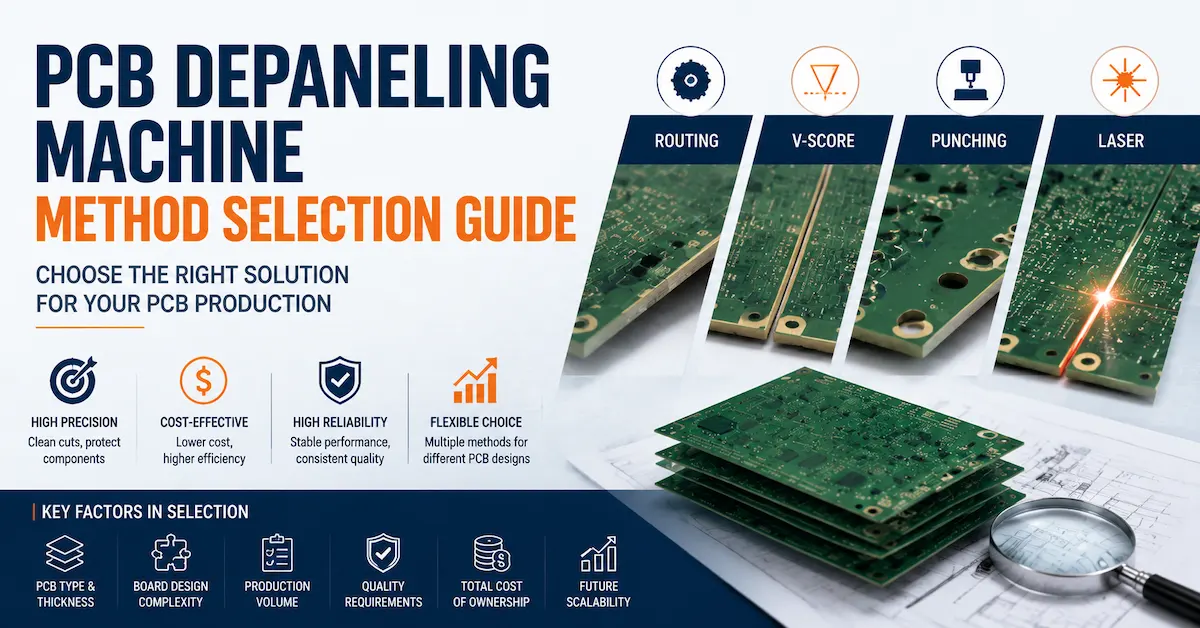
CHIKIN CNC's PCB depaneling method selection guide provides additional context for evaluating different separation approaches.
3. Start With PCB Panel Geometry, Not the Machine Catalog
One of the most expensive equipment-selection mistakes is requesting quotations before confirming the panelization design.
An Auto PCB V Cut Machine can only perform consistently when the panel geometry and machine capabilities are compatible.
The engineering review should cover several variables.
PCB material and stack-up
Identify the base material, overall thickness, layer structure, and any special features.
A simple two-layer rigid board and a thick multilayer rigid board may require different tooling conditions, groove design, and inspection criteria.
Internal copper layers, copper-to-edge spacing, and material behavior should be considered when defining the permissible groove depth.
The presence of copper near the score line can introduce additional design and quality risks.
Panel length and width
The maximum PCB panel dimensions must fit the machine's actual processing and loading envelope.
Buyers should distinguish between:
-
Maximum supported panel dimensions.
-
Usable cutting length.
-
Fixture or conveyor clearance.
-
Panel border requirements.
-
Available positioning travel.
-
Space needed for loading and unloading.
A machine may accept a panel physically while lacking sufficient travel or tooling clearance for a particular groove arrangement.
Score-line location and orientation
A conventional V-scoring process is most straightforward when grooves follow continuous straight lines.
Important questions include whether the machine processes longitudinal and transverse scores, whether the panel must be rotated, and whether the required score lines can be reached without interference.
A panel containing multiple closely spaced score lines may create different requirements from a panel with one central separation line.
The buyer should provide a mechanical drawing showing the score locations rather than relying only on the board's external dimensions.
Component and copper clearance
When final separation occurs after assembly, components near the score line may experience mechanical strain.
Ceramic capacitors, certain solder joints, and other mechanically sensitive features deserve particular attention.
Clearance requirements depend on the panel construction and actual separation process. A universal minimum distance should not be assumed without reviewing the relevant design requirements.
Residual web thickness
For a simplified double-sided scoring geometry:
Residual web thickness = PCB thickness − upper groove depth − lower groove depth
For example, the relationship shows that changes in either groove depth influence the material remaining between the grooves.
This is a geometrical expression, not a recommended process setting.
The actual acceptable web thickness depends on PCB construction, customer specifications, handling requirements, and the subsequent separation method.
It should be verified through measurement and production trials.
Panel support and flatness
A panel that bends, shifts, or vibrates during processing may produce inconsistent results even when the cutter itself is accurately positioned.
The machine must support the PCB adequately for the intended operation.
Ask how the equipment manages panel warpage, edge support, clamping pressure, and movement during cutting.
These details often have a greater influence on real production quality than the appearance of the machine enclosure.
4. How Many Cutters Do You Need: Single, Four, Six, or Eight?
Cutter count is an important commercial comparison, but it should never be treated as a direct measurement of production capacity.
The first question is how the cutters are arranged and used.
A machine with several cutters might process different positions in one cycle, perform sequential operations, or use tools with different functions. The actual arrangement must be confirmed from the machine configuration.
CHIKIN CNC currently presents single-cutter and several multi-cutter product options.
Single Cutter PCB V Cut Machine
The Single Cutter PCB V Cut Machine is worth evaluating when a factory prioritizes straightforward operation, lower process complexity, or flexible handling of different panel jobs.
For lower-volume production, the main economic advantage may be avoiding unnecessary machine complexity.
A single-cutter configuration can also be useful when the number of separation paths is limited.
However, a simpler cutting arrangement does not automatically mean the machine has a lower total cost. The quotation, fixtures, changeover requirements, and available automation functions must still be reviewed.
4 Cutter Auto PCB V Cut Machine
The 4 Cutter Auto PCB V Cut Machine is positioned within CHIKIN's multi-cutter equipment range.
This option may be relevant when the factory needs a more repeatable production station and expects enough workload to justify a multi-cutter arrangement.
The manufacturer's published product description identifies an enclosed industrial configuration and emphasizes controlled V-cut processing.
Before choosing this equipment, request confirmation of the actual cutter arrangement, whether cutter positions are adjustable, supported panel formats, and measured processing time.
6 Cutter Auto PCB V Cut Machine
The 6 Cutter Auto PCB V Cut Machine is presented as an enclosed industrial processing system for repeatable PCB panel operations.
Its product page describes a touchscreen interface, a status indicator, and a guarded working area.
For procurement teams, these features are relevant to daily operation, but the critical questions remain the operating mechanism, tool engagement, available cutting envelope, maintenance needs, and achievable cycle time.
The number six should not be interpreted as proof of six independent processing lanes.
8 Cutter Auto PCB V Cut Machine
The 8 Cutter Auto PCB V Cut Machine is another option for buyers evaluating repetitive rigid PCB processing.
Its product description emphasizes multiple cutters, enclosed operation, controlled loading, and consistent processing.
This makes it worth considering for larger or more repetitive workloads, subject to technical validation.
Before investing in a higher-cutter-count machine, the buyer should determine whether the panel geometry can actually utilize the available cutter arrangement.
Otherwise, extra hardware may add purchase and maintenance costs without producing a meaningful increase in accepted output.
Multi-cutter comparison table
| CHIKIN product option | Published cutter designation | Potential purchasing scenario | What must be verified |
|---|---|---|---|
| Single Cutter | 1 cutter | Flexible or lower-volume panel operations | Processing mechanism, panel range, cycle time |
| 4 Cutter Auto | 4 cutters | Repeated jobs requiring multi-cutter processing | Cutter positioning, simultaneous operation, changeover |
| 6 Cutter Auto | 6 cutters | Production-oriented panel processing | Actual cutter utilization, throughput, tooling access |
| 8 Cutter Auto | 8 cutters | High repetition and potentially demanding output requirements | Effective capacity, cutter layout, maintenance and ROI |
The table identifies published product configurations and possible evaluation scenarios. It does not represent verified speed, accuracy, cutter independence, or capacity rankings.
For a broader comparison, see CHIKIN CNC's single-cutter versus automatic PCB V-cut guide.
Buyer recommendation: Request one comparable sample-processing test for every shortlisted configuration. The winning machine is the one that produces acceptable boards at the required rate with manageable operating costs.
5. How to Calculate Real Production Throughput
Many equipment comparisons focus on a nominal machine speed without considering the complete production cycle.
For industrial buyers, the important metric is the number of acceptable panels or individual boards produced during a real operating period.
A machine may process the groove quickly but lose time during loading, alignment, unloading, inspection, or changeover.
Calculate the complete cycle
A simplified production cycle can be expressed as:
Total cycle time = Loading + Positioning + Cutting/Separation + Unloading + Other recurring cycle activities
Where operations overlap, actual elapsed time should be measured rather than simply adding independent task durations.
For a multi-cutter machine, the cutting component must reflect its real operating sequence and the number of tools that are effectively used.
Calculate effective hourly output
A practical calculation is:
Effective panels/hour = (3,600 ÷ measured cycle time in seconds) × operating availability
To estimate acceptable individual boards:
Accepted boards/hour = Effective panels/hour × Boards per panel × First-pass yield
Consider a hypothetical production example:
| Variable | Illustrative assumption |
|---|---|
| Total measured cycle time | 30 seconds per panel |
| Operating availability | 80% |
| Individual boards per panel | 8 |
| First-pass acceptable yield | 98% |
Calculation:
3,600 ÷ 30 = 120 theoretical panels/hour
120 × 0.80 = 96 effective panels/hour
96 × 8 × 0.98 = approximately 753 accepted boards/hour
This example demonstrates a calculation method only. It is not a published performance result for any CHIKIN model.
The same formula can be applied to measured trial results from different machines.
Why more cutters do not guarantee higher output
Suppose two machines have different cutter counts but process the same panel.
The machine with more cutters may reduce cutting time. However, if loading, positioning, and unloading take most of the cycle, the improvement in total output may be much smaller than expected.
Similarly, frequent product changes can reduce utilization if the multi-cutter arrangement requires more time to reconfigure.
Buyers should therefore request:
-
Measured complete cycle time.
-
Number of PCB panels processed during the test.
-
Actual board quantity per panel.
-
Changeover time between different products.
-
Operator interventions per production period.
-
Downtime causes.
-
Scrap and rework results.
-
Cutter replacement or adjustment frequency.
These measurements provide a more useful purchasing comparison than a claim such as “high-speed automatic production.”
6. Technical Specifications That Matter Most
Not every Auto PCB V Cut Machine product page provides a complete, text-based specification sheet.
CHIKIN's publicly accessible V-cut listings do not establish a consistent set of verified numerical specifications across the single-, four-, six-, and eight-cutter configurations.
Buyers should therefore request a model-specific technical datasheet before making commitments.
| Specification | Why it matters | Recommended verification |
|---|---|---|
| Maximum and minimum panel size | Determines board compatibility | Drawing review and sample fit test |
| Supported board thickness | Influences cutter engagement and tooling | Test representative minimum and maximum thicknesses |
| Process type | Distinguishes scoring from separation | Operating diagram and machine demonstration |
| Cutter quantity and arrangement | Influences possible process sequence | Tool-layout drawing |
| Cutter material and geometry | Influences cutting behavior and wear | Tool specification and replacement procedure |
| Groove depth or separation control | Affects finished-board quality | Measured production samples |
| Positioning method | Influences alignment and repeatability | Repeated panel trials |
| Feeding and handling | Influences cycle time and labor | Complete cycle observation |
| Power and utility requirements | Determines factory compatibility | Final electrical and utility drawing |
| Extraction requirements | Affects process cleanliness | Utility specification and operating demonstration |
| Operator interface | Influences setup and changeover | HMI demonstration |
| Safety features | Affects safe operation and compliance | Guarding and interlock review |
| Machine dimensions and weight | Determines installation feasibility | Approved general arrangement drawing |
| Software and data compatibility | Influences programming and integration | File and interface verification |
These are RFQ requirements, not claims that every listed feature is included in every machine.
Cutter geometry and blade condition
Cutting quality is influenced by the condition and geometry of the working tool.
Depending on the process, relevant variables may include blade angle, edge condition, alignment, cutting engagement, and feed behavior.
A worn tool can increase cutting forces, damage laminate edges, or produce inconsistent grooves.
Ask the manufacturer how cutters are inspected, replaced, aligned, and maintained.
Positioning and repeatability
Machine positioning should be evaluated under actual processing conditions.
An impressive control resolution does not guarantee the same accuracy on the finished PCB.
Panel rigidity, tool condition, fixture alignment, and mechanical behavior all affect the final result.
Instead of accepting a general accuracy statement, define the measurement points and acceptance tolerances in the purchase specification.
Changeover capability
If the factory processes different PCB designs, changeover efficiency may be a decisive factor.
Ask how operators change cutter spacing, fixtures, processing programs, and positioning references.
A machine with lower nominal speed but shorter changeovers can outperform a more complex machine in a high-mix production environment.
7. How Automatic V-Cut Processing Affects PCB Quality
The purpose of automation is not simply to remove material or divide boards more quickly.
The process must preserve the electrical, mechanical, and dimensional requirements of the PCB.
Several quality risks should be considered during equipment selection and qualification.
Inconsistent groove depth
If the groove depth varies along the panel, the residual web may also vary.
This can cause inconsistent separation behavior, premature panel breakage, or excessive force during final depaneling.
Potential contributing factors include material-thickness variation, positioning errors, cutter wear, panel warpage, and unstable support.
A practical inspection plan should measure representative positions along the groove, not only one point.
Edge burrs and laminate damage
Unsuitable tooling or process conditions may leave burrs, rough edges, or localized damage.
For rigid laminate, excessive mechanical forces can also contribute to cracking or delamination.
Buyers should inspect representative samples using the methods required by their quality system.
A visually smooth edge alone may not demonstrate that internal damage is absent.
Misaligned upper and lower grooves
For double-sided scoring, the relationship between the two groove positions matters.
If the grooves are offset, the resulting residual material may not match the intended design.
This should be considered in the process specification and sample-inspection plan.
Excessive stress during separation
Depaneling transfers mechanical forces into the board.
If the board bends excessively, sensitive components and solder connections may experience damaging strain.
The appropriate test method depends on the product's reliability requirements.
For higher-reliability assemblies, the customer may specify additional strain evaluation, magnified inspection, or electrical testing.
Particle generation and contamination
Mechanical cutting can generate particles that must be managed appropriately.
The extraction arrangement, cleaning practices, and work-area design should be compatible with the production environment.
An enclosed cabinet is useful, but the presence of an enclosure alone does not prove a particular level of dust containment or extraction performance.
Practical quality-control checklist
| Inspection point | What the engineer should evaluate |
|---|---|
| Groove geometry | Correct location, depth and consistency |
| Residual web | Agreement with the approved panel specification |
| Groove alignment | Upper/lower path relationship where applicable |
| Finished edge | Burrs, chips, roughness and visible laminate damage |
| Panel stability | Adequate strength before the intended separation stage |
| Separation behavior | Controlled breakaway without excessive bending |
| Component condition | No unacceptable cracking, movement or solder-joint damage |
| Repeatability | Stable results across representative production samples |
Inspection acceptance limits must come from the customer's drawing, applicable product requirements, and agreed qualification plan.
For rigid printed boards, relevant IPC design, performance and acceptability documents can inform the broader quality system. However, the purchase specification must identify the applicable editions and requirements. Compliance cannot be inferred from the machine's product category.
8. Factory Acceptance Testing: What Overseas Buyers Should Require
Factory Acceptance Testing, or FAT, is one of the strongest ways to reduce equipment-purchasing risk.
A buyer should not rely exclusively on photographs, a short promotional video, or an unqualified maximum-speed figure.
The acceptance process should demonstrate whether the equipment can process the buyer's actual PCB panels to an agreed standard.
Stage 1: Approve the application specification
Before FAT, the buyer and supplier should agree on:
-
Intended operation: V-scoring or final separation.
-
PCB material and stack-up.
-
Representative panel drawings.
-
Board thickness and dimensional limits.
-
Required groove or separation characteristics.
-
Expected production rate.
-
Inspection methods.
-
Acceptable defect criteria.
-
Required machine utilities.
-
Safety and operating requirements.
Without this agreement, both parties may interpret a successful test differently.
Stage 2: Test representative production samples
Use panels that represent actual production, not only the easiest design to process.
Where relevant, include a typical panel and a more demanding panel within the proposed operating range.
The test should use approved tooling, realistic operator procedures, and the same process configuration intended for delivery.
If the supplier is proposing several different machine configurations, test them under comparable conditions.
Stage 3: Record complete cycle performance
Observe the entire production sequence.
Measure loading, positioning, processing, unloading, and any recurring delays.
Record whether the machine operates with one operator, requires frequent manual adjustments, or experiences interruptions.
A standalone cutting-time claim should not be substituted for complete production-cycle data.
Stage 4: Inspect finished samples
Inspect the processed panels using the agreed method.
This may involve dimensional measurement, visual inspection, groove cross-sections, edge inspection, and separation testing.
If assembled boards are being processed, the qualification plan may also require checks related to component stress or functional performance.
Stage 5: Review maintenance and safety
Confirm that the supplier demonstrates routine cutter replacement, cleaning, setup, and fault handling.
Verify the specified guarding and safety functions, including emergency stops and interlocks where applicable.
Safety devices should be tested under the approved procedure without bypassing protective functions.
FAT acceptance matrix
| Test item | Evidence requested | Acceptance basis |
|---|---|---|
| Machine configuration | Equipment checklist and technical drawings | Approved purchase specification |
| Panel compatibility | Representative panel trial | Agreed sample list |
| Processing quality | Inspection report and retained samples | Customer-defined tolerances |
| Cycle time | Recorded complete-cycle measurements | Agreed output target |
| Repeatability | Results from repeated processing | Approved statistical or dimensional criteria |
| Cutter maintenance | Demonstrated replacement procedure | Approved maintenance requirements |
| Safety operation | Functional verification record | Applicable safety requirements |
| Operator training | Training demonstration or records | Contract scope |
| Documentation | Manuals, drawings and spare-parts list | Delivery checklist |
A FAT does not automatically guarantee future production performance, but it provides a documented basis for equipment acceptance.
For buyers importing machinery, retaining videos, measurement records, sample identifiers, and signed reports can also help resolve technical questions after delivery.
9. Production Line Integration and Factory Requirements
An Auto PCB V Cut Machine should be evaluated as part of an overall PCB production process, not as an isolated cabinet.
A technically suitable machine can still become a bottleneck if its loading arrangement, utility requirements, or maintenance access do not fit the factory.
Determine where the machine belongs
If the equipment creates V-scores during PCB fabrication, its location should correspond to the approved board manufacturing sequence.
If it separates populated PCB panels, the installation should align with the SMT and downstream assembly workflow.
That distinction determines how panels enter and leave the work area and what handling precautions are necessary.
Standalone versus inline operation
A standalone machine may be appropriate when production quantities are moderate or jobs change frequently.
Inline operation may become attractive when the factory needs repeatable transfers between connected production stages.
However, inline integration requires more than placing a conveyor beside the machine.
Buyers should confirm panel transfer height, direction, handshaking signals, fault behavior, upstream and downstream buffer capacity, and any required communication interfaces.
Do not assume that a machine supports SMEMA, MES connectivity, barcode tracking, or other interfaces unless the specific configuration has been confirmed.
Factory utilities and working environment
Before delivery, request the installation requirements for the actual model.
Important information includes electrical supply, compressed air if required, extraction connections, floor loading, access clearances, and any specified environmental limits.
The supplier should also provide the machine dimensions and service-access layout.
For international projects, verify local electrical compatibility and applicable machine-safety obligations before shipment.
Operator training and maintenance
Training should cover machine setup, normal operation, cutter handling, cleaning, alarms, and routine inspections.
Maintenance planning should include spare-part identification, tool replacement procedures, documentation, and support arrangements.
These items should be included in the commercial review rather than discussed only after the machine arrives.
10. Total Cost of Ownership: Look Beyond the Purchase Price
Equipment buyers frequently compare quotations without calculating the cost of producing an acceptable PCB.
For a fair comparison, capital cost should be evaluated together with actual productivity, tool consumption, labor, downtime, and quality losses.
Main ownership-cost categories
| Cost category | Examples |
|---|---|
| Initial investment | Machine, required options, fixtures and installation |
| Tooling | Cutters, replacement tools, alignment and servicing |
| Labor | Loading, unloading, inspection, setup and changeover |
| Utilities | Electricity, compressed air and extraction |
| Maintenance | Preventive service, consumables and spare parts |
| Quality losses | Scrap, rework, edge defects and damaged assemblies |
| Production interruptions | Unplanned downtime and delayed orders |
| Support and training | Operator training and technical assistance |
Calculate cost per acceptable board
A simplified comparison is:
Cost per accepted board = Total relevant operating cost ÷ Total accepted boards
For longer-term comparisons, allocate the machine's capital cost over the assumed ownership period and expected production volume.
Include the same cost categories for every shortlisted machine.
A lower-priced machine may be economical if it comfortably meets production requirements.
A higher-priced multi-cutter model may be justified if documented productivity gains, lower scrap, or reduced handling costs offset the additional investment.
Neither outcome should be assumed before testing.
Evaluate the cost of changeovers
A factory producing the same board all day may benefit from an optimized fixed setup.
A high-mix EMS operation may care more about rapid fixture changes and simple programming.
For that reason, production schedule and product variety are essential parts of equipment selection.
The correct purchasing objective is not the lowest quotation or the maximum number of cutters.
It is the lowest sustainable cost per acceptable board while meeting quality, safety, and delivery requirements.
11. How to Evaluate an Auto PCB V Cut Machine Manufacturer
Choosing a supplier involves more than confirming that a product appears in a catalog.
The manufacturer should be able to explain how its machine processes the customer's actual panels and which operating conditions have been verified.
Engineering communication
A technically useful supplier should be willing to review panel drawings, discuss the scoring or separation mechanism, and explain application limitations.
If a supplier cannot identify whether a machine creates grooves or separates existing grooves, the buyer should resolve that uncertainty before proceeding.
Model-specific information
Ask for a complete datasheet covering the quoted model and configuration.
Avoid relying on general company-level specifications for machine-specific performance.
If options are proposed, distinguish standard equipment from optional components in the quotation.
Sample-processing capability
Ask whether the manufacturer can conduct a sample trial using the customer's PCB panels and inspection requirements.
Clarify sample quantities, test conditions, reporting, and any trial-related costs before arranging the test.
After-sales support
For overseas buyers, support arrangements should be documented.
Confirm training, troubleshooting channels, spare-parts availability, warranty scope, exclusions, and the process for resolving technical problems.
A supplier's marketing statement about global support is not a substitute for a defined service agreement.
CHIKIN CNC as a supplier option
CHIKIN CNC supplies PCB processing and automation equipment, including drilling, routing, V-cut-related machinery, laser processing and inspection equipment.
For V-cut applications, its published range includes single-cutter and multi-cutter options.
This gives PCB equipment buyers several product configurations to review within one supplier's portfolio.
The most useful next step is to have CHIKIN's technical team assess the customer's panel drawings, target output, intended process stage, and installation requirements.
Specific cutter geometry, throughput, working limits, customization availability, and warranty terms should be confirmed through the model-specific quotation and technical documentation.
12. Common Purchasing Mistakes and How to Avoid Them
Mistake 1: Confusing V-scoring with final depaneling
A machine that creates grooves may not perform final separation of an assembled board.
Better approach: Define the exact manufacturing operation before requesting quotations.
Mistake 2: Selecting equipment only by cutter count
More cutters are not automatically more productive if the panel layout cannot use them effectively.
Better approach: Compare actual cycle time and acceptable output using identical sample panels.
Mistake 3: Ignoring residual web requirements
Incorrect groove depth can affect handling strength and separation behavior.
Better approach: Include the required score geometry and inspection criteria in the drawing package.
Mistake 4: Assuming all rigid PCB materials behave alike
Board thickness, material construction, copper placement, and mechanical properties influence process requirements.
Better approach: Qualify representative materials and stack-ups.
Mistake 5: Overlooking assembled-board stress
A depaneling process may create damaging strain even when the visible board edge appears acceptable.
Better approach: Evaluate sensitive components and use additional inspections where product reliability requires them.
Mistake 6: Buying based on maximum speed claims
Maximum processing speed may exclude loading, unloading, changeovers, and downtime.
Better approach: Calculate effective accepted output from measured complete cycles.
Mistake 7: Ordering without a documented FAT
Without agreed acceptance criteria, technical disagreements become harder to resolve after shipment.
Better approach: Include FAT requirements in the purchase agreement.
13. Auto PCB V Cut Machine RFQ Checklist for International Buyers
A complete Request for Quotation helps suppliers recommend relevant equipment and reduces the risk of comparing incompatible offers.
Before contacting CHIKIN CNC, prepare the following information.
| RFQ field | Information to provide |
|---|---|
| Intended process | V-scoring, pre-scored board separation or other specified operation |
| PCB material | FR4 or other actual material designation |
| PCB stack-up | Layer count, thickness and relevant construction details |
| Panel dimensions | Minimum, maximum and common sizes |
| Score drawing | V-line positions, orientation and groove requirements |
| Panel layout | Boards per panel and product variants |
| Process stage | Bare-board fabrication or post-assembly processing |
| Component restrictions | Sensitive components, edge clearances and handling limits |
| Production target | Required panels or accepted boards per hour |
| Product mix | Number of models and expected changeover frequency |
| Quality requirements | Dimensional tolerances, inspection and acceptance criteria |
| Automation | Standalone, operator-assisted or inline requirements |
| Factory conditions | Electricity, air, extraction, space and installation country |
| Service needs | Training, documentation, warranty and spare parts |
| Project timing | Target FAT, shipment and installation schedule |
Example message to send to the supplier
Subject: Auto PCB V Cut Machine RFQ for Rigid PCB Production
Dear CHIKIN CNC Team,
We are evaluating an automatic PCB V-cut solution for our rigid PCB production line.
Our application details are as follows:
-
Required process: [V-scoring / Separation of pre-scored panels]
-
PCB material: [Material and stack-up]
-
Board thickness: [Thickness range]
-
Panel dimensions: [Length × Width]
-
Score-line arrangement: [Drawing attached]
-
Required output: [Panels or boards per hour]
-
Production schedule: [Shifts per day]
-
Automation requirements: [Standalone / Inline]
-
Installation location: [Country]
Please recommend a suitable machine configuration and provide the technical datasheet, cutter arrangement, sample-testing options, estimated production cycle, installation requirements, and commercial quotation.
We would also like to discuss factory acceptance testing, operator training, and spare-parts support.
Best regards,
[Name / Company]
Buyers can send their application requirements through the CHIKIN CNC contact and quotation page.
A complete drawing package and clear production targets will make the technical discussion more productive than a quotation request based only on machine names.
14. Frequently Asked Questions
What is the difference between an Auto PCB V Cut Machine and a PCB depaneling machine?
An automatic V-scoring machine creates V-shaped grooves in a PCB panel, typically during bare-board fabrication. A depaneling machine separates individual boards along existing score lines or other designed separation features.
Some product listings use these terms broadly. Buyers should confirm the actual mechanism and the production stage supported by the specific machine.
Is an 8 Cutter Auto PCB V Cut Machine always faster than a 4 Cutter model?
No. A higher cutter count does not guarantee proportionally higher output.
Performance depends on cutter engagement, panel layout, setup time, processing sequence, loading, unloading, and operating availability.
Compare complete-cycle measurements using the same representative PCB panels before selecting a configuration.
Can an automatic PCB V-cut machine process multilayer FR4 boards?
Potentially, provided the particular machine supports the material, thickness, stack-up and required groove or separation geometry.
Multilayer construction introduces additional considerations, including internal copper clearance and finished-board quality.
The application should be reviewed with the supplier and qualified using representative panels.
Can the machine process flexible PCBs?
Conventional V-scoring is generally more appropriate for suitable rigid PCB panels than for flexible circuits.
Flexible PCB separation often requires other methods because flexible substrates do not behave like rigid laminates during scoring and breakaway.
For FPC applications, alternative processes such as routing or laser cutting may be more appropriate after engineering evaluation.
How is V-score depth verified?
Groove depth and residual web can be evaluated using appropriate dimensional measurement or cross-sectional inspection methods.
The acceptance method and tolerances should be defined before production.
Measurements should cover representative locations and repeated samples rather than relying on a single visual observation.
Can V-cut equipment be used after SMT assembly?
It depends on whether the equipment performs final separation and whether the assembled PCB design is suitable for that process.
Post-assembly separation requires particular attention to nearby components, solder joints, board support, and mechanical strain.
A machine designed only for creating V-scores during fabrication should not be assumed to perform assembled-board depaneling.
How do I calculate the capacity of an automatic PCB V-cut machine?
Measure the complete time required to process one panel, including recurring loading and unloading operations.
Convert that cycle into theoretical panels per hour, then adjust for actual operating availability.
To calculate acceptable board output, multiply by boards per panel and the measured first-pass yield.
This gives a more realistic comparison than maximum cutter-speed figures.
What specifications should I request before purchasing?
Request the machine's operating principle, cutter arrangement, supported panel sizes, material and thickness limits, relevant processing tolerances, utility requirements, complete-cycle performance, machine dimensions, and safety provisions.
Also request maintenance documentation, available spare parts, warranty terms, and sample-testing arrangements.
Do not treat unspecified parameters as standard features.
Is automatic V-cut processing suitable for a high-mix PCB factory?
It can be, but the answer depends heavily on changeover frequency and panel compatibility.
A factory processing a small number of repeated panel designs may benefit from a more specialized multi-cutter arrangement.
A high-mix factory should place greater emphasis on fixture flexibility, setup time, programming requirements, and operator workload.
What should be checked during factory acceptance testing?
A meaningful FAT should verify machine configuration, actual panel compatibility, processing quality, repeated-cycle performance, operating controls, relevant safety functions, and required documentation.
The test should use customer-representative panels and mutually agreed acceptance criteria.
An operating demonstration alone is not equivalent to a complete FAT.
How can I get a suitable CHIKIN CNC V-cut equipment recommendation?
Prepare the PCB panel drawing, material, thickness, score-line layout, intended process, production volume, and quality requirements.
Then contact CHIKIN CNC to discuss the appropriate equipment configuration and request a technical review.
You can begin with the CHIKIN CNC equipment catalog or submit your requirements through the official inquiry page.
Conclusion
Selecting the right Auto PCB V Cut Machine begins with understanding the PCB manufacturing process, not choosing the machine with the most cutters.
For rigid PCB production, the important factors are panel geometry, scoring or separation requirements, cutter arrangement, tooling compatibility, repeatability, quality control, and effective production throughput.
A single-cutter configuration may be sufficient for some operations, while a multi-cutter machine may offer advantages for repeated panel layouts and demanding production schedules. The appropriate choice depends on measured performance, product mix, and total ownership cost.
Before placing an order, PCB manufacturers and overseas purchasing teams should confirm the intended machine function, request model-specific specifications, evaluate representative samples, and establish clear factory acceptance requirements.
CHIKIN CNC provides several V-cut-related equipment options for industrial PCB processing applications. Buyers can review the available single-, four-, six-, and eight-cutter product pages and discuss their particular production conditions with the manufacturer's technical team.
Planning to upgrade your PCB V-scoring or panel separation process?
Share your PCB panel drawings, board material, score-line layout, target output, and factory requirements with CHIKIN CNC.