



550 x 1250mm PCB Drilling and Routing Machine Overview
The 550 x 1250mm PCB Drilling and Routing Machine is designed for shops that need a compact but capable platform for board processing, prototyping, and small-batch production. For buyers, the main challenge is usually the same: how to handle accurate drilling, contour routing, and repeatable panel work without tying up larger production equipment. This machine format addresses that problem with a dedicated working area, a gantry-style processing structure, and an external operator station that keeps the workflow organized on the shop floor.
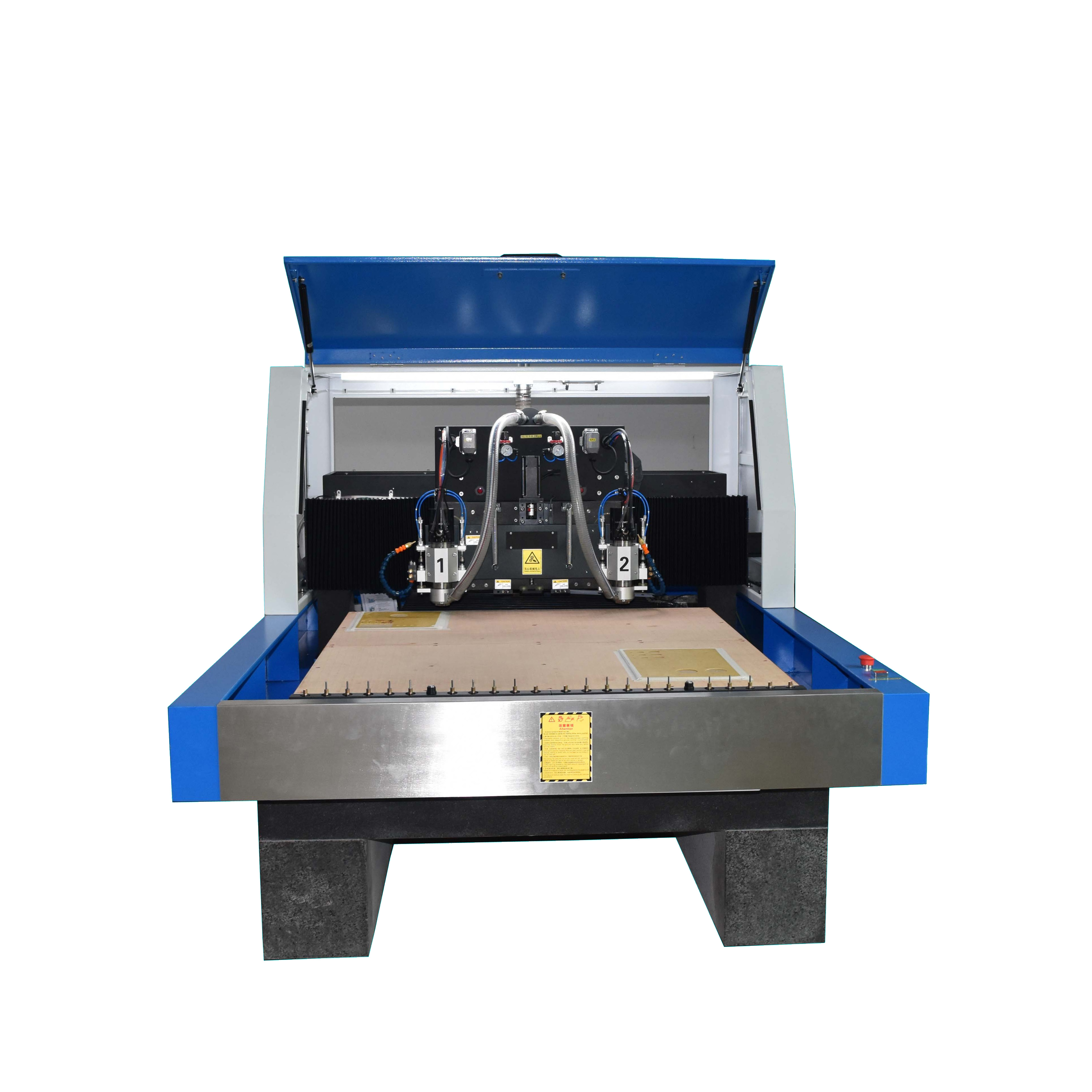
In practice, this type of machine is often considered alongside a PCB routing machine or PCB CNC routing machine when teams need controlled, automated handling of flat materials. The visible machine structure suggests a heavy-duty enclosed system built for industrial use, with front loading access and a table that supports sheet-based processing. While exact performance figures are not provided, the layout itself signals a focus on stable operation and practical production handling.
Product Overview
This machine is presented as a 550 x 1250mm-format solution for board-related machining tasks. The footprint makes it suitable for smaller production lines, lab environments, and fabrication rooms that need reliable processing without a full-scale line. The enclosed working zone helps keep the process contained, while the side-mounted monitor and keyboard create a separate operator point for program loading, setup, and run control.
For buyers comparing PCB manufacturing equipment, the useful question is not only what the machine can do, but how smoothly it fits into daily production. A machine like this is valuable when the workflow includes drilling points, profile routing, and repetitive shaping of flat stock. The visible dual-head layout may indicate higher throughput or multi-tool flexibility, though the exact operating mode is not confirmed.
Machine Specification
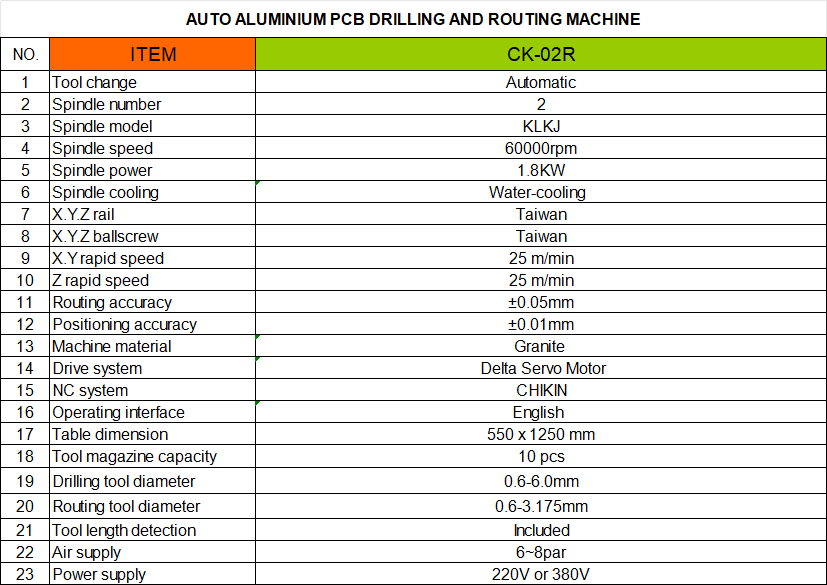
Key Capabilities and Visible Structure
Working Area and Loading
The 550 x 1250mm format gives a clear clue about the intended processing envelope. That size is often chosen for sheet-fed work where operators need enough length for panels, nested parts, or grouped board layouts. The front-access opening supports straightforward loading and unloading, which can reduce handling time during short production runs.
Gantry and Head Assembly
The machine includes a bridge-style gantry over the work surface with two visible head modules. Those modules may support drilling, routing, or another tool-based process, but the exact configuration is not identifiable from the data. What can be stated safely is that the structure is built for controlled movement over a flat bed, which is a core requirement for a PCB drilling and routing equipment setup.
Operator Station
A dedicated console with monitor and keyboard indicates a workflow designed for direct machine supervision. That is useful for setup changes, job selection, and monitoring production without crowding the work zone.
Materials and Finish Options
The visible machine body appears to be built from metal frame sections, painted panels, and dark internal enclosure surfaces. That kind of construction is common in industrial fabrication machinery because it helps support rigidity and routine shop use. The work surface looks like a sacrificial or replaceable bed, though the exact material cannot be confirmed.
For end-use applications, this machine category is typically associated with flat sheet materials and board-style workpieces. Since exact material compatibility is not supplied, it is best to evaluate the final setup based on the actual drill, spindle, or routing head configuration provided by the manufacturer.
Manufacturing Process and Machine Build
From a production standpoint, machines in this category are usually assembled through welded frame construction, sheet metal fabrication, precision machining, electrical wiring, and electromechanical integration. The goal is to create a stable platform that resists vibration and keeps motion consistent across the working area. The enclosed gantry and heavy base visible here align with that industrial approach.
If your team is sourcing a circuit board routing machine, the build quality matters as much as the motion system. A rigid frame helps with alignment during repetitive operations, while a clean control layout simplifies training and day-to-day use.
Application Scenarios
This machine format can be used in several shop-floor settings where flat material processing is routine:
PCB prototyping and small-batch board preparation
Panel cutting and edge profiling for custom fabrication
Sign making and decorative routing work
Cabinetry components, templates, and fixture parts
Shop-floor production of foam, plastic, wood, or composite parts, where appropriate
Because the exact cutting system is not confirmed, these applications should be understood as typical use cases for this class of machine rather than guaranteed performance claims.
Quality Control and Buyer Decision Factors
When evaluating a machine like this, buyers should look closely at rigidity, table flatness, access to the working area, control interface, and serviceability. For electronics-related routing work, consistency of movement and safe handling of dust or debris are especially important. If the machine is meant for PCB routing machine duties, also confirm the controller setup, tool compatibility, and the method used for drilling and contour cutting.
It is also worth asking how the two visible heads function. If they are independently usable, that may improve process flexibility. If they are fixed tool modules, they may be intended for a narrower workflow. Clarifying this early helps buyers match the machine to actual production needs.
Customization Guidance
Before ordering or specifying a build, define the board sizes, material types, required hole patterns, and production volume. Those inputs will shape the final machine configuration more effectively than a generic spec sheet. Buyers should also confirm enclosure access, dust extraction needs, control software compatibility, and whether the machine will be used for drilling, routing, or both.
For teams looking at PCB manufacturing equipment, the safest approach is to request configuration details based on the real workflow rather than assuming standard features. Tooling, fixtures, and software integration often determine the machine’s true value on the shop floor.
Request a Quote or Configuration Review
If you are comparing a 550 x 1250mm PCB Drilling and Routing Machine with other fabrication options, start with the workpiece size, process type, and daily output target. Share those requirements with your supplier so the final machine matches your production line. If you need help selecting a suitable setup for drilling, routing, or general flat-panel processing, send your application details and ask for a configuration review.