


Automatically IC Programming for Electronics and Burner Test Workflows
Automatically IC Programming is used to reduce manual handling, shorten setup time, and improve repeatability when programming chips or verifying electronic modules in production. In a factory environment, the main problem is not only writing data to an IC, but also keeping each device aligned, connected, and traceable while avoiding operator mistakes. A properly designed IC Writer or IC Burner Machine helps solve that by holding the device securely, managing the signal path, and supporting stable programming or test operations.
Product Overview
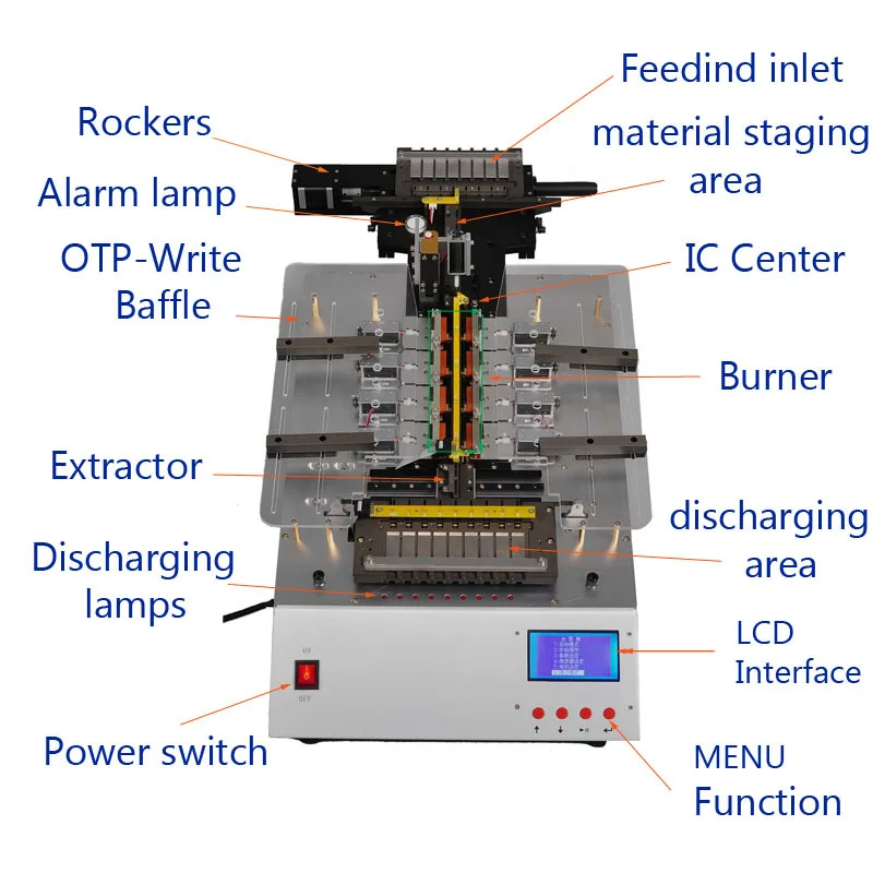
The supplied product information suggests an industrial cabinet-style machine with a slanted working face, integrated display, push buttons, exposed wiring, and multiple repeated contact or clamping modules. That layout is consistent with an automated electronics fixture, a PCB test station, or a specialized control interface used in manufacturing and service work. Some visible labels also point to burner-related functions such as a burner power socket and signal cable holder, so the platform may be used for industrial control or diagnostic testing rather than a consumer device.
Because the image-based information is limited, the exact model and final function should be treated as uncertain. Still, the visible structure clearly indicates a purpose-built industrial machine for controlled electrical connection, signal routing, and operator-guided testing.
Machine specification
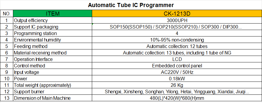
Key Capabilities and Visible Configuration
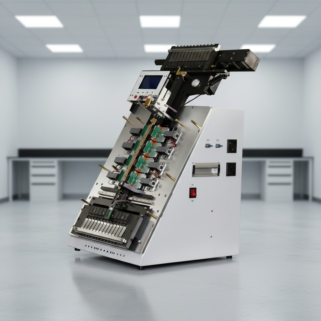
Rigid enclosure and angled working face
The machine uses a metal cabinet with white painted side panels and black internal hardware. The inclined geometry is practical for line operators because it improves visibility of the contact area and display while keeping the work surface compact. This type of structure is often chosen for fixture-based programming or testing where the board, chip carrier, or burner interface must be loaded from the front.
Integrated HMI and manual controls
A front-mounted display panel and physical push buttons are visible, along with a red switch. These components suggest local control for step-by-step operation, status checking, or fault clearing. For production teams, a simple operator interface is often more useful than a complex console because it reduces training time and makes the machine easier to integrate into an assembly line.
Multiple contact and cable management points
Repeated modules, cable harnesses, sockets, and holders are visible inside the frame. In an electronics workflow, these details matter because stable contact pressure and organized routing directly affect programming reliability, signal integrity, and serviceability. In a burner-related workflow, the same structure supports power connection, signal transfer, and cable positioning during setup or diagnosis.
Materials and Finish Options
The visible machine appears to use painted sheet-metal panels, structural brackets, rails, fasteners, and internal mounting plates. For this type of equipment, common build choices include steel frames for stiffness and coated panels for basic corrosion resistance. Depending on the application, the enclosure can also be adapted with different surface finishes, panel colors, access doors, cable glands, or protective covers.
When buyers evaluate an IC programming platform or a burner interface rig, finish matters less than mechanical stability and easier maintenance access. Removable side panels, accessible wiring paths, and clearly separated control zones are all practical advantages in daily use.
Manufacturing and Integration Process
Machines in this category are usually built as custom integration projects or semi-standard industrial systems. A typical process includes frame fabrication, enclosure assembly, electrical wiring, board mounting, control panel installation, and final functional checks. For an IC programming machine, the final step may include fixture alignment and contact verification. For a burner-focused unit, it may include wiring confirmation, switch operation testing, and signal path validation.
Careful cable routing and service access are important because production equipment is often opened for maintenance. A good layout reduces downtime and helps technicians isolate a fault without dismantling the full cabinet.
Application Scenarios
IC programming and PCB verification
An IC Burner Machine or chip burner can be used in semiconductor packaging, PCB assembly, device setup, and rework stations where consistent chip loading and reliable signal contact are required. The fixture-style design supports repeated operations and can be adapted for debugging, burn-in, or functional verification.
Industrial burner diagnostics and control testing
The visible burner labels indicate a second likely use case: burner system interface, calibration, or diagnostics. In that setting, the machine may serve as a controlled connection point for power and signal cables during test or maintenance work. Buyers in heating equipment, combustion control, and industrial servicing may value this arrangement because it organizes the interface between the operator and the burner assembly.
Quality Control and Buyer Decision Factors
When selecting this kind of equipment, buyers should focus on fixture rigidity, access to wiring, clarity of operator controls, repeatability of the contact system, and ease of maintenance. They should also confirm supported board size, connector layout, electrical requirements, and the exact operating purpose before ordering. Since the exact rating and software function are not supplied here, these points must be confirmed during technical review.
For production use, ask whether the machine can be adapted to your board, chip carrier, or burner interface, and whether the control logic matches your line procedure. If programming repeatability is critical, request details on fixture alignment and contact reliability. If the unit is for burner work, confirm compatible cable standards and service access requirements.
Customization Guidance
Custom builds are common for automatic electronics fixtures and burner test stations. Typical options include fixture plate changes, HMI layout adjustments, cable holder positioning, label updates, and enclosure modifications for line integration. If your process includes an IC programming step, the programming socket arrangement and operator workflow should be defined early. If the machine is for burner testing, the power socket, signal cable holder, and switch positions should be matched to the target assembly.
Contact Us for Technical Review
If you need an Automatically IC Programming solution, a custom IC Writer setup, or a specialized interface machine for burner-related testing, send your board drawings, cable requirements, and workflow description. A clear technical brief makes it easier to match the fixture design to your production or service process.