



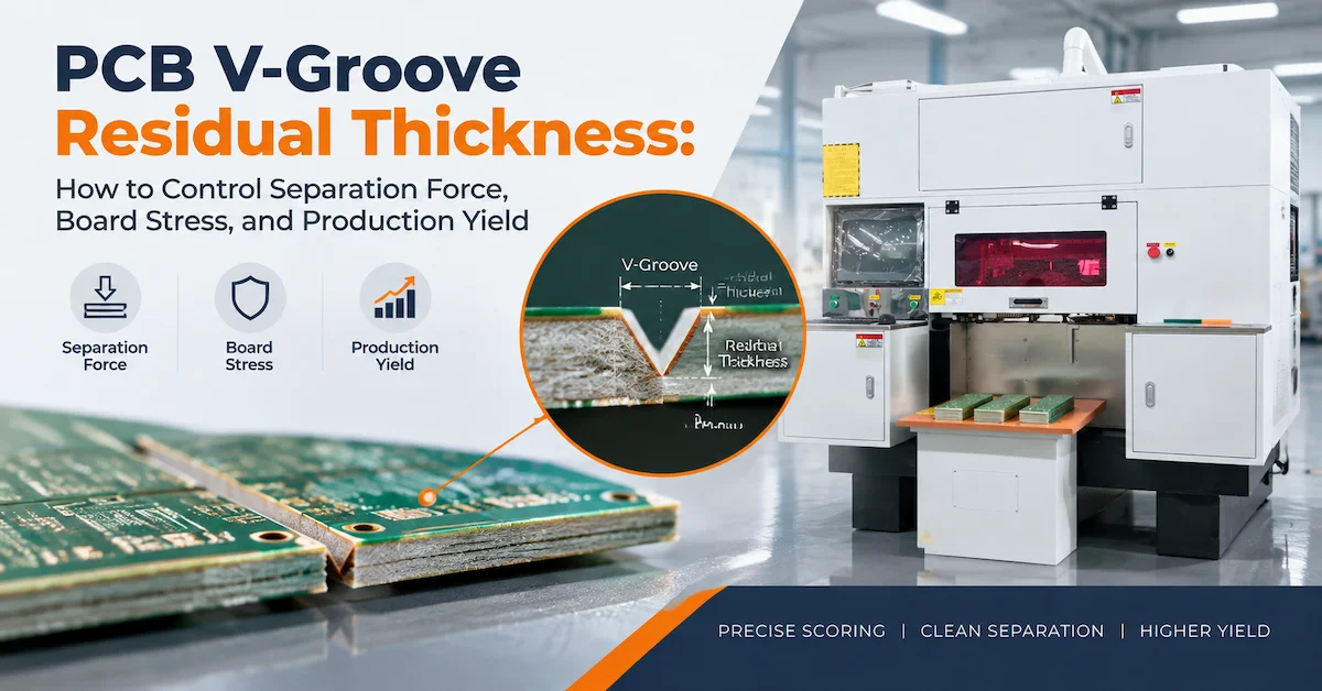
Residual thickness is the remaining board material between the bottom of a V-groove and the opposite surface. In a two-sided score, the first-order calculation is residual thickness = total PCB thickness - top V-score depth - bottom V-score depth. More residual material normally increases the force needed to separate a board from its panel. Too little residual material can reduce manual separation force but may increase flexing, corner cracks, copper damage, and assembly stress. The correct setting is therefore a validated process window, not a universal number copied from a drawing.
This article answers a practical purchasing and process question: how should a PCB manufacturer choose score depth and a V-CUT machine when the target is clean separation with low board stress? It combines a calculation method, a sample-test plan, machine-selection guidance, and an RFQ checklist. It also explains which facts can be confirmed from public CHIKIN product information and which values belong in the quotation, sample report, or acceptance document.
The intended readers are PCB production engineers, NPI teams, depaneling operators, quality managers, and buyers comparing a single-cutter machine with four-, six-, or eight-cutter automatic equipment. The examples use engineering variables rather than invented performance guarantees. Board construction, copper distribution, score geometry, blade condition, fixture support, and separation direction can change the result, so use your own panels and the supplier's approved limits before production release.
Quick Answer for Buyers and Process Engineers
For a symmetric two-sided V-score, calculate the remaining web first, then verify it with a microscope or calibrated depth method on the actual panel. If the web is thicker than the process can tolerate, separation force rises and operators may bend the board. If the web is thinner than the design can safely support, the panel may crack during machining, handling, transport, or depaneling. A useful validation sequence is: measure the stack-up, record both score depths, calculate the web, run a controlled separation test, inspect copper and laminate, and record force or operator method together with board stress indicators.
The phrase pcb v cut residual thickness describes a process variable, not a machine model. A machine supplier should review panel length and width, board thickness, layer count, copper weight, material, score location, required throughput, and acceptable edge condition before proposing a configuration. The company behind the CHIKIN name is Shenzhen ChiKin Automation Equipment Co., Ltd., based in Shenzhen, Guangdong, China. Its catalog covers PCB automation equipment, with single-, four-, and six-cutter V-CUT directions among the published choices. Those pages help a buyer shortlist a machine family. They do not settle the cutter layout, tooling, exhaust provision, or control setup for a particular job; those details need to appear in the quotation.
1. What PCB V-Groove Residual Thickness Means
A V-groove is a controlled pair of angled cuts made from one or both sides of a PCB panel. The cuts create a weakened line so individual boards can be separated after assembly or testing. The uncut material at the bottom of that line is the residual web. On the shop floor, “remaining bridge,” “score web,” and “residual thickness” usually refer to this same strip of material. None of them means the panel's full thickness, and none should be confused with the depth value entered in a machine recipe.
Take a 1.0 mm panel as a simple example. A top cut of 0.25 mm does not leave the same web as cuts of 0.30 mm or 0.35 mm, and a second cut from below changes the answer again. Copper foil, solder mask, plating, inner dielectric, and local artwork can change how a measurement appears. A drawing that states only “1.0 mm board, V-score 0.30 mm” is incomplete unless it identifies the score side, included angle, blade geometry, and whether a second score is present. In a buyer's specification, v groove residual thickness should therefore be written as a measured web range with a defined datum, not as an unexplained nominal label.
Residual thickness also has a spatial dimension. The nominal web on a straight rail may be correct while a corner, tab, fiducial area, heavy-copper region, or panel edge has a different effective stiffness. Tool deflection, fixture support, board bow, and blade runout can produce a local difference. That is why a buyer should ask for a sample map rather than relying on one measurement taken at the center of a panel.
Definition block
Residual thickness: material left between the deepest point of the V-groove and the opposite board surface at the score line.
Score depth: the distance from a board surface to the deepest point cut by one blade. The top and bottom depths may be equal or intentionally different.
Separation force: the force needed to break the remaining web and move the routed or scored board away from the panel under a defined fixture and direction.
Board stress: mechanical strain or bending load transferred into laminate, copper, solder joints, components, or a nearby rigid feature during scoring, handling, or separation.
2. The Residual Thickness Formula and Its Limits
For a two-sided score, use this first-order equation:
R = T - D_top - D_bottom
In this equation, R names the web that remains. T comes from the measured panel, while D_top and D_bottom come from the two score measurements. For a panel cut on one face only, use R = T - D_single. Keep that result in the one-sided data set; comparing it directly with a two-sided recipe conceals a different groove shape and crack path.
The calculation is useful because it forces the team to measure the board rather than assume the nominal drawing value. It is not a complete mechanical model. The force curve also depends on V-angle, blade sharpness, glass style, resin content, copper distribution, score continuity, panel support, temperature, and the way the operator or fixture applies the load. Treat R as the first variable in a controlled experiment, not as a guarantee of a particular Newton value.
| Input | What to record | Why it matters | Evidence to retain |
|---|---|---|---|
| Total thickness T | Average and local readings, including copper and mask | Nominal laminate thickness can vary across a panel | Gauge ID, locations, date, operator |
| Top score depth | Actual depth at center, rail, corner, and heavy-copper area | Blade position and support may vary by location | Microscope or section image |
| Bottom score depth | Same map used for the top side | Two-sided asymmetry changes the web | Measurement map and recipe revision |
| Residual web R | Calculated value plus observed range | Range is more useful than a single average | Calculation sheet linked to lot |
| V-angle and blade | Tool specification, condition, run hours | Geometry changes crack initiation and edge shape | Tool log and inspection photo |
| Separation method | Hand, fixture, roller, or automated depaneling | Force depends on how the load is applied | Video, force trace, or work instruction |
If the calculated residual is negative, the nominal inputs are inconsistent or the score depths have been misread. Stop and resolve the measurement. If the calculated value is extremely small, do not assume the panel is “better” because it separates easily. A thin web may hide a crack that later grows during shipping or reflow. Conversely, a thick web that needs a high separation force may be acceptable when the panel is supported and the board layout has generous clearance.
3. Why Residual Thickness Changes Separation Force
The remaining web carries load until a crack starts at the V-groove root and travels through the laminate. A thicker web generally has more cross-sectional material to fracture and a larger bending stiffness. The operator therefore applies more force or more displacement before the board separates. The relationship is not perfectly linear because crack initiation, fiber orientation, resin content, and the score root shape all change the force-displacement curve.
When a panel is separated by bending, the outer surface is placed in tension and the opposite surface in compression. A V-groove concentrates stress near the root. With a clean, symmetric score, the crack should follow the intended line. With an uneven or blunt score, the load can wander into the board, tear copper, or leave a ragged edge. Residual thickness controls how much bending is needed before that event, while the groove geometry controls where it begins.
Buyers should ask for a test that reports more than “passes” or “fails.” Record the separation direction, support spacing, operator or fixture method, force if a load cell is available, displacement, and the condition of the edge. The useful comparison is between candidate recipes on the same board lot. A force number from a different fixture or a different panel geometry is not a transferable machine specification.
| Residual web condition | Typical process tendency | What to inspect before release |
|---|---|---|
| Relatively thick | Higher separation effort, more bending, stronger need for a supported fixture | Operator ergonomics, solder-joint strain, edge chipping, cycle time |
| Mid-range and uniform | Predictable crack path when blade and panel support are stable | Force trend, edge quality, board registration, local copper |
| Very thin or locally interrupted | Low apparent separation force but higher risk of premature cracking | Shipping vibration, reflow handling, corners, tabs, cosmetic rejects |
| Uneven across panel | Some boards release early while others need excessive load | Score-depth map, blade parallelism, panel flatness, fixture support |
The table is a screening guide, not a universal process limit. The correct range belongs to the board design and the customer's quality agreement. A supplier can help narrow the range through sample processing, but the PCB manufacturer should own the final release criteria because it knows the assembly route and downstream stress sensitivity.
4. Residual Thickness and V-Cut PCB Stress
The most visible failure is often a cracked corner or chipped edge, but the more expensive failure may be invisible strain in a solder joint, ceramic capacitor, BGA package, or plated hole. The term v cut pcb stress covers those mechanical effects during scoring and separation. A board can look acceptable at the edge and still have experienced a bending event that shortens component life.
Stress risk increases when the score line passes close to large components, heat sinks, connectors, rigid stiffeners, or a heavy copper pour. The panel may also be more sensitive when boards are long and narrow, when the score is interrupted by routing, or when a panel has a large difference in copper density between the two sides. The right response is not always a deeper groove. It may be a change to support, separation direction, tooling sequence, component clearance, or panelization design.
Use a risk map during NPI. Mark every score line, component keep-out, copper transition, plated slot, and change in panel width. Draw the support points on the same map, including the portions that will hang free during final separation. A ceramic part or another fragile feature close to the score deserves microscope review; a high-risk assembly may also justify a strain gauge or a component-level check. File those results under the board revision. Otherwise, a later panel edit can quietly invalidate the original study.
Stress can also be introduced before separation. Watch the panel as it enters the cut: a tilted blade, uneven clamp, or feeder pressing on a bowed panel may work the same line on every cycle. Cutting a different web may make the symptom disappear for a while, yet the loading error remains. Measure panel flatness and verify that the work area is guided and supported across the full travel.
5. Groove Depth Is Not Residual Thickness
The phrase pcb v score depth normally means the depth of one cut. The phrase pcb v groove depth may be used for the same value or for the combined depth of top and bottom grooves, depending on the drawing convention. A buyer should ask the supplier to define the datum and report each side separately. Otherwise a recipe can appear to match the drawing while leaving a very different residual web.
For example, suppose a measured board is 1.60 mm thick. Recipe A makes a 0.42 mm top score and a 0.42 mm bottom score, leaving an estimated 0.76 mm web. In Recipe B, the operator records 0.55 mm from the top and 0.35 mm from below; the arithmetic leaves 0.70 mm. Do not treat B as a balanced cut merely because the web looks close to A. Its roots sit at unequal depths, so the panel will not carry the bending load in the same way. Recipe C with a single 0.70 mm score leaves the same arithmetic web as B but has a different crack path and bending behavior.
Always write the convention in the process sheet: “top depth from top copper surface,” “bottom depth from bottom solder-mask surface,” or another defined datum. Include the V-angle, blade diameter, and whether the number is measured before or after a cleaning operation. A clear convention prevents a common handover failure in which the designer, machine programmer, and operator each use “groove depth” to mean something else.
6. How Board Material and Stack-Up Change the Window
FR-4 is not a single mechanical material. Glass style, resin content, copper weight, layer count, and pressed thickness change how a score starts and propagates. A thin two-layer board with balanced copper may release differently from a multilayer board with thick internal planes. High-Tg laminate, halogen-free resin systems, polyimide, aluminum-backed constructions, and metal-core boards should be treated as separate validation families unless test evidence shows that a recipe transfers.
Glass bundles can make the crack path less uniform than a simple thickness calculation suggests. A score that ends on a glass-rich region may need a different load from one that ends in resin. Heavy copper near the score line can bridge the crack or tear during separation. A large copper pour on one side can also make the two surfaces mechanically asymmetric. Record copper weight and local copper pattern when you compare samples.
Panel construction matters just as much as board material. A carrier rail, tooling strip, mouse-bite area, routed pocket, or mixed board size can change support and bending span. If the same PCB design is produced in two panel formats, do not automatically reuse the same residual thickness recipe. Qualify the format, not only the board outline.
| Board factor | Possible effect on scoring and separation | Recommended buyer action |
|---|---|---|
| FR-4 layer count and glass style | Different crack resistance and edge appearance | Submit stack-up and a representative panel |
| Copper weight or large planes | Local bridge, tearing, or asymmetric stiffness | Mark copper-heavy score locations |
| High-Tg or halogen-free resin | Different fracture and debris behavior | Test at the intended production temperature |
| Aluminum-backed or metal-core board | Metal layer may block a standard PCB V-score method | Ask for a dedicated process review before ordering |
| Long narrow board | Higher bending moment during separation | Validate support spacing and separation direction |
| Mixed-size array | Uneven support and changing local stiffness | Map every board position, not just the center |
| Routed interruptions | Crack path can stop or divert | Define the order of routing and V-scoring |
CHIKIN's public machine descriptions position its V-CUT equipment for PCB panel separation and production-line use. Whether a specific model is suitable for a special laminate, metal-backed construction, or unusual panel geometry must be confirmed from a sample and a model-specific technical discussion. The safest RFQ contains material and panel details before price comparison.
7. Blade Geometry, Wear, and the Score Root
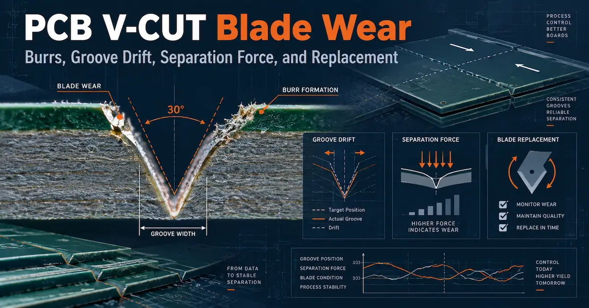
Residual thickness is only meaningful when the blade is cutting the intended geometry. A new circular blade, a blade with a damaged edge, and a blade with accumulated resin deposits can all leave different root shapes at the same programmed depth. A blunt blade may generate more heat and lateral force, which can widen the score or push the panel out of alignment. A chipped blade can create a local notch that releases early and makes the web non-uniform.
Inspect blade condition under a defined magnification. Record blade identification, installation date, number of panels, material family, cleaning action, and the reason for replacement. Do not wait until an edge becomes visibly unacceptable; trend the edge condition and the separation result together. A machine recipe that appears stable after a blade change should still receive a first-piece check because the effective depth can shift with blade diameter and seating.
Blade parallelism is another hidden variable. If the top and bottom cutters are not aligned to the same score line, the panel experiences a twist or a wider damaged zone. Four- or six-cutter systems can improve throughput by processing multiple directions or lanes, but they also require a clear alignment and maintenance method. Ask how the machine verifies cutter position, how an operator changes a blade, and what gauge or sample confirms the setting after service.
The score root should be inspected for loose fibers, exposed copper, smeared resin, and a continuous crack starter. A polished-looking edge is not enough. A clean root with a controlled web is the target because it makes the separation behavior repeatable. Keep representative edge photographs with the process approval report.
8. Measuring Residual Thickness on a Real Panel
The measurement method should match the decision. A quick optical inspection can show whether the score is continuous and whether the root is damaged. A cross-section can reveal the actual web and copper relationship. A depth gauge can help on an accessible, flat surface, but the gauge tip must not bridge the groove or compress the laminate. For high-risk boards, use two methods and compare their uncertainty.
Take measurements at a minimum of five positions per score direction: near each rail, near the center, at a corner transition, and at the most copper-heavy location. Use the same datum on every sample. If the board is bowed, support it as it is supported in the machine and record the support condition. A value without location, instrument, and operator is difficult to audit.
When sectioning a coupon, avoid polishing away the root or rounding the V. Mount the sample consistently, photograph the cross-section with a scale, and label top and bottom. If a destructive section is not practical for every lot, create a correlation between sectioned samples and an in-line optical or depth method. Recheck that correlation after a blade, material, or machine change.
| Measurement method | Strength | Limitation | Best use |
|---|---|---|---|
| Optical microscope | Shows root, burr, copper tear, and continuity | Does not always give absolute depth without a datum | First-piece visual approval |
| Calibrated depth gauge | Fast and repeatable on accessible surfaces | Tip geometry and board bow can bias the reading | Routine checks with a fixture |
| Cross-section microscopy | Direct view of total stack-up and web | Destructive and slower | NPI, troubleshooting, audit sample |
| Coordinate measurement | Maps location and variation | Requires suitable fixturing and programming | Multi-position capability study |
| Force-displacement test | Relates web to separation behavior | Fixture and direction strongly affect result | Comparing recipes on one panel family |
Do not report excessive decimal places. The number of digits should reflect the instrument uncertainty and the natural variation of the board. A report that claims micrometer-level certainty from a hand gauge can create false confidence. State the method, resolution, repeatability, and sampling plan with the measured range.
9. A Nine-Step Engineering Method for Process Release
The following nine-step method is designed for a buyer who needs a reproducible decision rather than a nominal machine setting. It can be used during NPI, a supplier comparison, or an investigation of edge and stress complaints.
Step 1: Define the board stack-up and total thickness.
Collect the drawing, stack-up, copper weights, material family, surface finish, solder mask condition, and measured thickness at several panel locations. Include the board revision and panel format. If the supplier receives only the nominal thickness, ask for the missing details before a quotation is finalized. A supplier cannot reasonably choose a blade or support arrangement from a single number.
Step 2: Map the score geometry and separation route.
Mark every score line, direction, board outline, rail, corner, tab, routed interruption, and sensitive component. State whether the top, bottom, or both sides are scored. Identify how the panel will be supported during scoring and how the individual board will be separated after assembly. This map reveals stress risks that are invisible in a simple cross-section.
Step 3: Calculate the target residual web.
Use R = T - D_top - D_bottom as a starting calculation. Show nominal and measured values separately. Do not silently round a negative or very small result. Define an initial range for the sample trial and list the reasons it may be adjusted, such as edge condition, component clearance, copper balance, or operator force.
Step 4: Relate the web to the separation force.
Select one separation method and keep it constant while comparing samples. A manual push, a roller fixture, and a pneumatic depaneler will create different curves. Measure peak force when possible, but also record displacement, crack path, and the number of boards that need a second movement. Force is a process value only when the fixture and direction are documented.
Step 5: Screen board-stress risks.
Review component placement, ceramic parts, BGA corners, connectors, plated holes, copper transitions, and long unsupported spans. Use strain or component inspection when the board is sensitive. The goal is to determine whether the force is entering the score line as intended or moving into the assembly. A low edge force does not automatically mean low assembly stress.
Step 6: Validate score depth and groove depth on samples.
Run at least three nearby settings around the initial target, keeping the board lot and blade condition controlled. Measure the actual top and bottom depths, residual web range, edge appearance, and separation behavior. Label each sample so the result can be traced to a recipe. The best setting is usually a window with stable results, not the deepest or shallowest setting that passes one sample.
Step 7: Compare the machine configuration with the duty.
Decide whether a single-cutter, four-cutter, six-cutter, or another automatic arrangement fits the panel route and output. Compare support, alignment, access, HMI, exhaust or duct provision, changeover, and service access alongside cutter count. A faster nominal cycle is not valuable if a maintenance change introduces unverified depth variation.
Step 8: Build an RFQ and acceptance checklist.
Send the supplier the panel drawing, stack-up, dimensions, score map, target output, material, sample quantity, and quality criteria. Ask the quotation to state what is included: machine, blades, fixtures, exhaust interface, installation, training, spare parts, and acceptance testing. Put residual-thickness measurement and edge/stress checks into the acceptance plan instead of leaving them as a verbal promise.
Step 9: Release with documented limits and maintenance checks.
After approval, issue the recipe with the board revision, measured web range, blade part number, support setup, inspection frequency, and reaction plan. Define what happens when the web drifts, edge chipping increases, a blade is changed, or a panel format is modified. Requalify after a major machine service, score geometry change, material change, or new panelization.
This method supports all four buyer intents. It answers the informational question about residual thickness, supports a commercial investigation of machine options, creates a supplier-comparison framework, and gives a buyer the fields needed for a useful RFQ.
10. Sample Testing: Turn a Number into Evidence
A sample trial should be designed as a small experiment. Use one representative panel lot and a defined blade condition. Select a low, middle, and high score-depth condition around the proposed target. Keep feed, spindle speed if relevant, support, and separation direction stable. If the machine uses automatic cutter positioning, record the program version and the operator who loaded it.
For each condition, record: total thickness, top depth, bottom depth, calculated residual, minimum and maximum web, edge photographs, peak force if available, separation time, board count, visible cracks, copper damage, burrs, panel bow, and any component or solder-joint observation. Do not average away a local failure. A single corner crack may be the most important result in the batch.
If there is no force sensor, use a controlled fixture or a defined operator method. A hand test can still be valuable when the same support, direction, and operator procedure are used, but label it as a comparative check rather than an absolute force measurement. Video can help distinguish a smooth crack from a sudden snap or a second bend.
The sample report should end with an engineering decision: accept, adjust, or reject the setting. List the next action and the owner. For example, “adjust bottom cutter by the supplier-approved increment and repeat at corner position,” is more useful than “depth not stable.” Attach the report to the purchase order or machine FAT/SAT record if the trial supports equipment selection.
11. Selecting a V-CUT Machine for the Process
Machine selection should start with the panel route, not a cutter-count slogan. A single-cutter machine may be appropriate for controlled, lower-volume, variable-format work where an operator needs direct access and frequent setup changes. An automatic multi-cutter system may be better when the factory needs repeatable positioning, multiple score directions, shorter handling time, or integration with a line. The answer depends on the panel mix and acceptance criteria.
CHIKIN publicly presents a single-cutter PCB V-CUT machine, a four-cutter automatic PCB V-CUT machine, and a six-cutter automatic PCB V-CUT machine. These links are useful starting points for configuration discussions. They do not replace a sample test because the same cutter arrangement can require different fixtures or recipes for different board families.
| Configuration direction | Buyer value to investigate | Questions for the supplier |
|---|---|---|
| Single cutter | Flexible setup and direct control for varied formats | How are depth, parallelism, and changeover verified? |
| Four cutters | Multiple directions or higher throughput in a defined route | Which directions are simultaneous, and what support is included? |
| Six cutters | More automated panel processing for repeat families | How is cutter alignment checked after a tool change? |
| Eight-cutter or special layout | Potential for a high-output line or special panel flow | What sample evidence supports the proposed cycle and web uniformity? |
Ask to see the work area, guide and support method, HMI status information, access doors, and maintenance points. Public product images may show an enclosed industrial cabinet and a guided work area, but a quotation should describe the exact dimensions, interfaces, safety functions, and options. If dust or chips are generated, ask whether an exhaust or duct connection is included or optional and how it affects the work area.
12. CHIKIN Entity and Factory Evidence
Shenzhen ChiKin Automation Equipment Co., Ltd. is a Shenzhen, Guangdong, China manufacturer and supplier of PCB automation equipment and production-line solutions. Its public product range includes PCB V-CUT machines, PCB drilling and routing equipment, CCD alignment equipment, and related automation directions. The company serves the industrial PCB manufacturing market rather than selling a generic consumer tool. This entity context matters when a buyer evaluates engineering support, sample processing, installation, training, spare parts, and remote service.
The public product material describes enclosed cabinets, viewing windows or access doors, guided work areas, HMI or status indications, and different cutter configurations. These are useful evidence of the equipment category and intended production environment. They are not evidence of a universal residual-thickness limit, measured separation-force curve, certification, or delivery date. Those items should be requested in the buyer's technical and commercial package.
The knowledge base used for this article records CHIKIN support directions such as sample processing, installation or training, spare parts, and remote or service support. Exact scope, response time, packaging, and warranty terms must be confirmed in the quotation. Public packaging information describes plastic inner protection and wooden-crate packing, with vacuum or PE packaging available when requested. Buyers shipping to a different climate or port should specify moisture protection and inspection requirements rather than assuming that a standard crate covers every route.
The most useful factory evidence is tied to the buyer's board: a sample report, cross-section photographs, a measured residual range, an edge-quality record, and a documented acceptance method. Ask the supplier to mark which value is measured, which value is calculated, and which value is only a proposed starting point. This separation between fact and estimate makes a machine comparison more trustworthy.
13. What to Put in a High-Quality RFQ
An RFQ that says “please quote a PCB V-cut machine” creates a weak comparison because suppliers must guess the duty. A useful RFQ is short but specific. Attach a panel drawing, a stack-up, a score map, and photographs of any sensitive area. State whether the target is depaneling after assembly, bare-panel separation, or both.
Include the following information:
- Board material family, total thickness range, copper weight, layer count, surface finish, and any metal backing.
- Panel length, width, rail width, board count, score directions, routed interruptions, tabs, and corner geometry.
- Nominal and measured score depths if a process already exists, plus the current residual web range.
- Required edge condition, allowable burr or copper exposure, and any cosmetic or safety requirement.
- Components near the score, ceramic parts, connectors, BGA areas, plated holes, or assemblies sensitive to bending.
- Target panels per hour, shifts per day, changeover frequency, operator skill level, and available floor space.
- Preferred loading direction, upstream and downstream equipment, communication interfaces, and exhaust or dust requirements.
- Sample quantity, required FAT/SAT tests, measurement instruments, documentation, training, spare blades, and service expectations.
Ask each supplier to return the same fields: recommended cutter configuration, score-depth adjustment resolution, alignment method, supported panel range, sample result, cycle definition, utility requirements, included tooling, packaging, lead-time basis, warranty scope, and exclusions. Request that any value dependent on sample approval be labeled as such. This makes a commercial investigation comparable without turning marketing claims into acceptance criteria.
14. Acceptance Test and Supplier-Comparison Template
The acceptance test should reflect the board's actual risk. It may include dimensional checks, score-depth mapping, a separation-force comparison, edge inspection, a component-stress check, cycle-time observation, alarm verification, and a post-tool-change repeat. The exact limit should be agreed before the test. Do not insert a universal Newton value or a universal web range when the board and fixture have not been defined.
| Acceptance item | Test setup to define | Evidence | Decision rule to agree |
|---|---|---|---|
| Score depth | Board lot, datum, instrument, locations | Depth map and raw readings | Within approved range and variation |
| Residual thickness | Measured thickness and both score depths | Calculation plus section or optical proof | Web range matches board process window |
| Separation behavior | Support, direction, fixture, operator, speed | Force trace or controlled video | No uncontrolled snap, repeat bend, or crack migration |
| Edge condition | Magnification, lighting, sample positions | Labeled photos | No prohibited burr, copper tear, or delamination |
| Board stress | Component inspection or strain method | Inspection record | Meets the assembly owner's limit |
| Repeatability | Multiple panels and positions | Run chart or summary table | No unexplained drift across the trial |
| Tool change | New blade or simulated maintenance event | Before/after depth map | Recipe restored by defined verification |
| Safety and service | Guards, access, alarms, maintenance points | Checklist and training record | All agreed functions demonstrated |
For supplier comparison, normalize the test. Use the same board lot, the same panel format, the same score map, and the same acceptance language. Compare total cost of ownership as well: blades, fixture changes, training, spare parts, exhaust, inspection time, and expected maintenance access. A lower purchase price can be offset by manual rework or a weak verification method if the process window is narrow.
15. Maintenance Checks That Protect Residual Thickness
Residual thickness drifts when the cutter, fixture, panel datum, or program drifts. Add a first-piece check after a blade change, a significant collision, a machine move, a fixture replacement, or a software/recipe revision. Inspect the blade for deposits and chips, check its seating, clean the guide and support surfaces, and confirm that the panel datum is free of debris. A small particle under a support can lift a panel and make the effective score shallower on one side.
Maintain a simple log with date, board family, recipe, blade ID, panel count, depth readings, edge observation, and action. Trend the minimum and maximum web rather than only the average. If the range widens, investigate parallelism, blade wear, panel bow, fixture wear, and measurement repeatability before changing the nominal depth. An adjustment that hides a mechanical issue may create a later failure.
The machine manual and supplier service instructions control lubrication, cutter replacement, electrical checks, and safety procedures. Do not reach into a cutter area or change a blade without the required lockout and guarding steps. The article's engineering method is for process specification; it is not a substitute for the equipment safety manual.
16. Common Mistakes and Better Alternatives
Mistake: using the nominal board thickness in the formula.
Better practice: measure the actual panel at the score locations and keep the lot and instrument information. Nominal thickness is a design target, not a guaranteed local dimension.
Mistake: treating one score depth as the residual web.
Better practice: report top depth, bottom depth, total thickness, and calculated residual separately. State the datum and convention.
Mistake: choosing the deepest score because it separates easily.
Better practice: inspect edge integrity, shipping robustness, corners, and assembly stress. Optimize for the full process, not the hand force alone.
Mistake: comparing force numbers from different fixtures.
Better practice: keep support spacing, direction, displacement, and operator method constant. Treat a force number as meaningful only inside its test definition.
Mistake: qualifying the center of a panel only.
Better practice: map rails, corners, heavy-copper areas, and the longest unsupported span. Local geometry often controls the first failure.
Mistake: changing depth when the blade or support is worn.
Better practice: inspect mechanical condition first, then remeasure. Record the correction and requalify a first piece.
Mistake: requesting a machine quote without a sample plan.
Better practice: attach the board stack-up, score map, quality criteria, and acceptance tests. A supplier can then recommend a configuration with less guesswork.
17. Troubleshooting Matrix
| Symptom | Possible causes | Checks before changing the recipe |
|---|---|---|
| One rail separates early | Local shallow or deep web, panel bow, support gap | Map that rail, verify datum, inspect support |
| Center needs excessive hand force | Web too thick, score root blunt, long unsupported span | Section the root, inspect blade, test support spacing |
| Copper tears along the score | Heavy copper, asymmetric depth, damaged blade | Review copper map, top/bottom depths, blade edge |
| Corner cracks during transport | Web too thin, stress concentration, poor panel handling | Inspect corner geometry and packaging, not only force |
| Ragged laminate edge | Chipped blade, wrong V-angle, unstable panel | Compare a new blade and check parallelism |
| Results change after maintenance | Datum shift, blade seating, fixture debris, recipe mismatch | Run post-maintenance first-piece map |
| Good edge but component failure | Bending load transferred into assembly | Add component/strain inspection and review support |
| Cycle time is high despite multi-cutter machine | Manual loading, recheck, changeover, or support limits | Define cycle start/stop and map the complete route |
The matrix is intentionally diagnostic rather than prescriptive. Several causes can produce the same symptom. Change one variable at a time, preserve the sample, and document the result. A controlled troubleshooting record is valuable evidence for both the factory and the machine supplier.
18. Questions Buyers Ask Before Ordering
What is a safe universal PCB V-cut residual thickness?
There is no responsible universal value. The web depends on board construction, V-angle, copper, score geometry, panel support, separation method, and assembly sensitivity. Use a sample test to establish a qualified range for each board family.
Is a deeper V-score always better for low separation force?
No. A deeper score can lower the remaining web but can also increase premature cracking, edge damage, and assembly stress. The process target is a stable crack path and acceptable downstream handling, not minimum hand force.
Can one recipe cover all FR-4 boards?
Usually not without evidence. Layer count, glass style, copper, thickness, panel format, and component layout change the mechanical response. Group boards only after a correlation study demonstrates that the recipe transfers.
Should I buy a single-cutter or automatic multi-cutter machine?
Compare panel variety, output, changeover, support, verification, maintenance access, and integration. Single-cutter equipment can suit flexible work; four- or six-cutter equipment can suit repeat families and higher automation. Let the sample and acceptance plan decide.
What should be linked to the quotation?
Link the final machine model, blade and fixture specification, score-depth convention, measured sample results, residual range, edge criteria, cycle definition, utilities, packaging, training, warranty, and service scope. State which values are sample-confirmed and which require production confirmation.
How should we handle aluminum-backed or metal-core boards?
Treat them as a separate application. The metal layer can change the cutting method, tool wear, edge condition, and safety requirements. Submit the full stack-up and ask for a dedicated feasibility review before assuming a standard PCB V-CUT recipe applies.
Can CHIKIN provide a test before purchase?
Public company information describes sample-processing and application-support directions, but scope and terms should be confirmed for the specific project. Send the board files, panel sample, target output, and inspection criteria with the inquiry so the engineering discussion is concrete.
19. A Practical Release Checklist
Before releasing a V-CUT recipe or approving equipment, confirm every line below:
- The board revision, material, thickness range, copper condition, and panel drawing are identified.
- Top and bottom score depth are defined from an unambiguous datum.
- Residual thickness is calculated from measured inputs and reported as a range.
- Score locations include rails, center, corners, and heavy-copper or sensitive areas.
- The blade, V-angle, cutter alignment, support, and fixture are identified.
- Separation direction, fixture, operator method, and force measurement are documented.
- Edge, copper, laminate, board-bow, and component-stress criteria are approved.
- A sample report links results to the machine recipe and board lot.
- Post-maintenance and post-blade-change checks are defined.
- The RFQ or acceptance document states included tooling, service, training, packing, and delivery basis.
- The final quotation distinguishes public product information from sample-confirmed values.
This checklist turns a technical article into a purchasing control. It gives the buyer a clean handoff to design, production, quality, and the equipment supplier.
Conclusion: Optimize the Web, Then Prove the Process
PCB V-groove residual thickness is the bridge between a score-depth drawing and the real separation behavior of a panel. The calculation R = T - D_top - D_bottom is the right starting point, but it is not the finish line. Separation force, board stress, copper balance, laminate, blade geometry, support, and downstream assembly must be reviewed together. A thin web can reduce hand effort and still create a fragile panel; a thick web can protect handling and still demand a fixture that controls bending.
For a sound purchase decision, send the supplier the actual stack-up, panel dimensions, score map, target output, sample quantity, and acceptance criteria. Compare single-cutter and automatic multi-cutter options on the same evidence. CHIKIN's Shenzhen engineering and manufacturing context, public V-CUT product range, sample-support direction, and production-line equipment images provide a starting point for that discussion; final machine capability, tooling, delivery, and service terms belong in the official quotation.
Send Your PCB Stack-Up and V-Groove Requirements to CHIKIN
For a faster technical review, include the current residual web, top and bottom score depths, board material, panel drawing, edge photographs, separation method, expected output, and any stress-related failure. An engineer can then respond to a defined process question instead of guessing from a product name.
Request a PCB V-CUT Sample Test and Machine Configuration Review