



During depaneling, an assembly rarely sees one neat, isolated load. It bends and twists; the two board surfaces move through tension and compression; the final release may add a short shock. The practical controls are close support, little uncontrolled deflection, an aligned tool and fixture, and a separation method suited to the panel. Prove the setup with populated assemblies, not just bare laminate. A clean-looking edge does not prove that a BGA corner, ceramic capacitor, solder joint, pad, or laminate interface escaped damage.
For a buyer, the real question is not “Which depaneling machine is fastest?” It is “Which machine and fixture can separate our worst-case PCBA without exceeding our approved strain, quality, and throughput limits?” That question belongs to four search intents at once. It is informational because the team needs to understand how damage occurs. It is a commercial investigation because V-CUT, routing, and laser systems create different load paths. It is a supplier comparison because the same board should be tested under the same acceptance method. It is RFQ intent because the result must become a measurable machine specification.
Process engineers and reliability teams will find the measurement detail here; SMT managers, quality leaders, and buyers can use the same evidence to compare offers. The working method has nine steps, followed by selection tables, inspection plans, supplier-evidence questions, FAT/SAT criteria, and an RFQ checklist. It does not invent a universal microstrain limit, component clearance, feed rate, MOQ, delivery date, or yield improvement. Those values depend on the assembly, component supplier requirements, customer standards, panel design, equipment configuration, and sample-test result.

Quick Answer: What Controls PCBA Stress During Depaneling?
Begin with five questions. Which method makes the cut? How close are fragile components? What supports the parent panel and the freed board? How far and how quickly does the board bend? Is the tool or score still in its qualified condition? Risk falls when the fixture carries the work, the cut follows its intended path, and the released board neither snaps nor twists. An instrumented sample then has to confirm the critical zones remain inside the customer-approved envelope. In an RFQ, PCBA separation stress should be linked to the submitted assembly, fixture, measurement method, and acceptance limit rather than described only as “low.”
The term pcb depaneling stress should therefore be treated as a measurable production characteristic, not a marketing phrase. Buyers should request a trial using the actual populated panel or a mechanically representative assembly. The supplier should document support points, machine recipe, tool condition, cut direction, strain-gauge locations when used, edge observations, cycle definition, and the result after a tool change or setup recovery.
1. What Depaneling Stress Does to a PCBA
Depaneling occurs late in the manufacturing route, after considerable value has already been added. By then, the panel may have crossed the printer, placement line, reflow oven, selective-solder station, cleaner, programmer, tester, and inspection bench. One bad bend can waste all of that work. More troubling is a unit that still passes the short factory test while a small crack waits for service vibration or thermal cycling.
The board does not experience one simple force. Near a separation line, the laminate may bend. At a corner, it may twist. A tab can hold one end of the board while another tab releases, creating a short shock. A hand tool can squeeze the edge. A worn router can add vibration. A V-score that breaks unevenly can pull the free board down as the operator lifts the remaining panel. Each event sends a different strain history into the assembly.
Component and interconnect risk is local. The same panel can show modest average deflection while a stiff connector, BGA corner, large ceramic capacitor, shield can, or heat sink creates a high local gradient. Package stiffness, pad design, solder alloy, laminate construction, copper distribution, component orientation, and temperature influence how the strain reaches the joint. That is why a rule based only on board thickness or component-to-edge distance is incomplete.
Definition: PCB depaneling stress
The mechanical load and resulting board strain created while a PCB or PCBA is separated from a manufacturing panel. It includes bending, twisting, tensile and compressive strain, vibration, impact, and fixture-induced loading.
Definition: separation event
The complete interval from the first cutter, blade, laser, punch, or manual load through final release and board handling. Measurement should include the snap or drop after the last attachment breaks, not only the cutting period.
Definition: low-stress process
A qualified process that keeps the assembly within product-specific strain and damage criteria under defined production conditions. “Low stress” is comparative and evidence-based; it is not a universal feature created by one machine name.
2. Why Damage Can Be Latent
Visible cracks and chipped edges are easy to reject. Latent damage is harder. A solder ball can contain a small crack that remains electrically continuous during a short end-of-line test. A pad can begin to crater below the solder mask while the component still functions. A multilayer ceramic capacitor can develop an internal crack with no immediate external mark. Later thermal cycling, vibration, handling, or installation can extend that damage.
This is why component damage during depaneling cannot be controlled by edge inspection alone. Inspection should follow the identified failure mode. A ceramic component may require optical review, electrical testing, and a destructive audit. A BGA risk may require strain characterization near package corners, daisy-chain monitoring on a test vehicle, X-ray for selected defects, dye-and-pry or cross-section analysis when justified, and review of the component or customer limit.
Latent risk also explains why a machine can appear stable during a demonstration with bare FR-4 and still be unsuitable for a populated product. Components and solder add local stiffness. Heavy connectors and shields change inertia. A thermally cycled PCBA may respond differently from a fresh bare panel. The supplier trial should reproduce the mechanical state of the production assembly closely enough to make the result meaningful.
| Potential failure | What may cause it during separation | Why visual edge inspection may miss it | Evidence to consider |
|---|---|---|---|
| Solder-joint crack | Board bending, fast snap, local twist | Joint remains hidden under package or lead | Electrical monitoring, microscope, cross-section, product test |
| Pad cratering or pad lift | Tensile strain near a stiff package | Damage begins within laminate under the pad | Strain data, destructive audit, component-area inspection |
| Ceramic capacitor crack | Board flex across a brittle body | Internal crack may have no surface mark | Electrical screening, acoustic or destructive analysis as appropriate |
| Trace or via damage | Crack path leaves score or tab | Copper discontinuity may be microscopic | Continuity test, cross-section, local microscopy |
| Laminate delamination | Tool load, heat, dull cutter, severe bend | Edge can conceal an internal interface defect | Sectioning, ultrasonic or other approved method |
| Connector or shield distortion | Unsupported mass during final release | Part may spring back after the event | Dimensional check, functional mating test, strain characterization |
3. How Solder Joints See Board Bending
Bend a board and its outer surface lengthens while the inner surface shortens. The attached parts have to follow that curve. A compliant lead can absorb some motion; a rigid area-array package or short, stiff termination may transfer more load into the joint and pad. The location and orientation of the part relative to the bend line matter as much as the overall board displacement.
The search phrase solder joint stress pcb often leads buyers toward a single allowable number. That is risky. Appropriate limits come from the product owner, component manufacturer, customer specification, reliability study, or approved internal practice. Strain magnitude matters, but strain rate and direction can matter too. A slow supported cut and a quick uncontrolled snap may reach similar peak deflection while presenting different risk.
Use a simple mechanical picture during process review. Draw the cut line. Mark the support points. Mark the portion that becomes free first. Add the heavy and stiff components. Then imagine the last attachment releasing. Does the board remain supported, or does its mass rotate around a remaining tab? Does the operator catch it, or does it fall? Does a clamp sit below a BGA? This drawing often reveals more than a machine brochure.
The relevant “PCB” in a stress discussion is the assembled system. Bare-board material, copper planes, solder mask, package bodies, underfill, shields, connectors, and local fasteners all contribute stiffness. Test the actual PCBA where feasible. When confidentiality or cost prevents that, build a mechanically representative coupon and document every difference from the production design.
4. Risk Factors Buyers Should Map Before Selecting Equipment
Start with a risk map rather than a machine list. Place the panel drawing beside the assembly drawing and identify features that can amplify bending or make the consequence of a crack more severe. The map should travel with the RFQ so every supplier evaluates the same problem.
High-priority features include BGAs and other area-array packages near a cut, multilayer ceramic capacitors oriented across a likely bend, large connectors, transformers, inductors, shield cans, heat sinks, press-fit features, tall components, heavy copper, thin board sections, narrow necks, and corners where a cut changes direction. Tabs that release in an uncontrolled order and long boards with little support also deserve attention.
Panel history belongs on the map. State whether the assembly has completed reflow, selective soldering, conformal coating, underfill, or mechanical fastening before depaneling. A coating can bridge a route or alter debris. A heat sink can add mass. An inserted connector can create a stiff boundary. If the production route has two depaneling stages, map both stages separately.
| Risk factor | Mechanism | Question for the buyer | Possible control |
|---|---|---|---|
| Sensitive component close to edge | High local curvature reaches package and pads | Which component limit governs approval? | Move feature, change cut path, add close support, use lower-contact method |
| Thin or narrow PCB section | Low bending stiffness | Where does the panel first flex during loading? | Dedicated nest, vacuum or mechanical support, controlled cut order |
| Heavy connector or shield | Inertia during final release | Is the component supported when the last tab breaks? | Capture fixture, alternate orientation, staged release |
| Unbalanced copper or asymmetric build | Board twists instead of bending evenly | Does the panel bow before the machine cycle? | Flatness control, compliant datum, vision alignment |
| Long V-score | Force accumulates along a straight line | Is the remaining web uniform? | Score verification, blade alignment, controlled support |
| Many routed tabs | Repeated load and final snap | Which tab should be cut last? | Programmed sequence, tab redesign, daughter-board support |
| Brittle or high-value assembly | Small damage has high cost | What evidence is required beyond visual inspection? | Strain study, electrical monitoring, destructive audit |
| Frequent product changeover | Fixture or recipe recovery error | How is the correct setup verified? | Recipe control, keyed fixture, first-piece validation |
5. Compare V-CUT, Routing, Laser, Punching, and Manual Breaking
No separation method is universally lowest stress. The best method is the one that fits the panelization and can be validated under the actual assembly conditions. A straight, well-controlled V-score can be efficient for repeat rigid boards. Routing provides freedom for irregular outlines and tabs but introduces tool force, vibration, and dust. Laser separation removes direct cutter contact but requires review of heat effects, material interaction, fumes, and economics. Punching can be productive with a dedicated die but transfers a rapid load and needs tight fixture control. Manual breaking has low capital cost but usually gives the weakest control over bending and operator variation.
| Method | Best-fit geometry | Main stress path | Process concerns | Evidence to request |
|---|---|---|---|---|
| V-CUT / V-score separation | Straight lines on suitable rigid panels | Bending and crack propagation along residual web | Score uniformity, blade alignment, board support, final snap | Web or depth map, fixture drawing, populated-panel strain trial |
| Router depaneling | Curves, slots, tabs, mixed outlines | Cutter force and vibration at each tab | Tool runout, wear, feed, entry path, dust extraction, support | Tool specification, path file, edge photos, strain trace |
| Laser depaneling | Thin, flexible, sensitive, or complex parts where validated | Minimal mechanical contact; thermal interaction remains | Heat-affected zone, fumes, material absorption, cycle and capital cost | Material trial, edge microscopy, thermal/process report |
| Punch / die separation | Stable high-volume geometry | Fast shear and impact through die | Dedicated tooling, alignment, wear, local shock | Tooling drawing, force method, strain and edge audit |
| Hand breaking / hand tool | Prototype or low-risk work only when approved | Operator-controlled bend and twist | High variation, ergonomics, repeated flexing | Work instruction, operator study, first-piece and audit data |
For low stress depaneling, do not select a technology from its generic label. Compare the complete production cell: loading, alignment, fixture support, cutter or beam path, sequence, extraction, unloading, and the state of the board after release. A laser may minimize mechanical force but may not suit every laminate or cost target. A router can be gentle when the board is captured close to the tool. A V-CUT system can be stable on the right straight-line panel and risky on the wrong assembly geometry.
6. The Nine-Step Method for a Low-Stress Depaneling Process
The following method turns a broad request for “less stress” into an engineering and purchasing workflow. Each step produces evidence that can be reviewed during supplier comparison and carried into production control.
Step 1: Define the assembled product and failure consequence
Start with the real assembly revision. Record PCB material, thickness, layer count, copper weight, panel size, board count, separation geometry, component population state, coatings, underfill, heat sinks, connectors, and other attachments. Identify the markets served, such as industrial control, automotive electronics, medical equipment, communications, lighting, or consumer products, because customer evidence and reliability expectations may differ.
List the failure modes that matter. A cosmetic consumer board and a safety-related controller do not carry the same consequence. State whether a latent solder crack, pad crater, MLCC crack, delamination, burr, dust residue, or dimensional shift triggers rejection. Attach the governing drawing, customer requirement, and component guidance where available.
Do not let the supplier guess what “good” means. If the team has no approved strain limit, define a characterization project rather than inventing one during the machine demonstration. The absence of a limit is a gap to close, not permission to use a generic internet value.
Step 2: Build a mechanical risk map
Overlay the panel outline, score or route, component locations, copper transitions, supports, and release sequence. Mark the nearest sensitive component to every separation feature. Note long unsupported spans and the board area that becomes free after each cut. For routing, number the tabs in intended order. For V-CUT, identify the orientation and which side is supported during the pass or break.
Use the risk map to select measurement positions. A strain gauge placed far from the critical package may report a quiet process while the package corner experiences the event. The map should also guide the fixture concept: support belongs where it interrupts the bending path without pressing on fragile components.
Review the risk map with design engineering. Sometimes the most economical stress reduction is a panel change: move a tab, rotate a capacitor, add a rail, widen a local section, change the release order, or provide a fixture-access keep-out. Equipment cannot fully compensate for panelization that forces the board to bend through a sensitive zone.
Step 3: Select the separation family from geometry and risk
Screen V-CUT, router, laser, and dedicated tooling against the actual outline. Straight pre-scored rigid panels may support V-CUT. Curves and internal features usually point toward routing or laser. Flexible circuits and unusually sensitive products may justify a non-contact trial. Very stable high-volume designs may support dedicated tooling when the impact and maintenance risks are validated.
Create a shortlist, not a predetermined winner. Estimate loading time, separation time, inspection, consumables, extraction, changeover, fixture cost, operator skill, maintenance, and expected product mix. A fast cycle on one board can become expensive when the factory changes models many times per shift.
Ask every supplier to explain the force path. Where is the parent panel held? Where is the daughter board held? What happens at the last attachment? How does the process react to panel bow? How is the cut aligned to the actual board? A credible answer should refer to the submitted panel, not only to machine accuracy.
Step 4: Design support and fixturing around the assembly
Fixtures control deformation. The ideal nest supports the board near the separation feature, avoids direct load on components, establishes a repeatable datum, allows debris removal, and captures the daughter board after release. It should not over-constrain a bowed panel or force it flat through a fragile component zone.
Document contact materials and replaceable wear parts. A hard support below a package may create its own stress concentration. A soft material may trap dust or change height over time. Vacuum support can help on some flat boards but may be interrupted by holes, components, or leakage paths. Mechanical clamps need defined force and location.
Include loading and unloading in the study. An operator can flex a panel while pushing it into a tight nest or pulling the finished board out. If the machine cycle is instrumented but manual handling is not, the largest event may occur outside the measured window. Video synchronized with strain data is useful for connecting peaks to specific actions.
Step 5: Plan cut direction, sequence, and final release
The sequence determines how stiffness changes during the cycle. A panel held on four sides at the start may behave like a cantilever after three sides are released. The final tab or score segment can then carry the mass of the entire board. Choose the order so support remains close to the active cut and the finished board does not rotate or fall.
For routing, review tool entry, exit, tab order, climb or conventional direction as permitted by the process, and movement between tabs. A sudden plunge next to a critical part may create a different vibration event from a smooth lead-in. For V-CUT, confirm the board orientation, score continuity, residual web or depth, blade overlap where applicable, and how the separated section is caught.
Program version control belongs here. Store the machine recipe with the board revision, fixture revision, tool, and approved inspection plan. A small path edit can change the mechanical event even when the final outline remains dimensionally correct.
Step 6: Establish a controlled tool and process window
Set candidate parameters through sample work, not guesswork. For a router, document tool diameter, flute geometry, stick-out, spindle speed, feed, entry method, tab size, and replacement rule. For V-CUT, document blade geometry, score condition, alignment, support, feed, and inspection after blade service. For laser, document source, power strategy, focus, passes, assist gas or extraction, and material-specific edge criteria.
The window should include tool life. A fresh router bit and a near-change-limit bit may produce different force and vibration. A clean V-CUT blade and a resin-loaded blade may not start the crack in the same way. Include beginning, stable mid-life, and defined end-of-life conditions in validation where risk justifies it.
Record utilities that influence stability. Extraction flow, compressed air quality, cooling, power, and ambient conditions may change results. The approved process should state which alarms stop the cycle and how an operator verifies recovery.
Step 7: Measure strain and the complete separation event
Use strain gauges or another approved method when the product risk requires quantitative evidence. IPC/JEDEC-9704A describes a methodology for strain-gauge testing of printed circuit assemblies and includes depanelization among operations that can induce board flexure. IPC's current status page lists IPC-9704B as a final draft for industry review at the time this article was updated. Buyers should confirm the applicable revision and their customer's requirements rather than treating this article as the standard itself.
Place gauges near the critical component locations selected from the risk map, following the qualified test method. Record sampling rate, gauge orientation, installation, data-acquisition equipment, filtering, event timing, and calculation convention. Capture loading, alignment, the full cut, last attachment release, unloading, and any manual handling. Report strain and strain rate in the format required by the product owner.
If strain gauges are not justified for a lower-risk product, build a disciplined comparative method. A displacement fixture, force trace, high-speed video, board-deflection gauge, or reference coupon can show whether one setup bends the board more than another. Label the result as comparative; do not convert it into an unsupported component strain guarantee.
Step 8: Inspect, test, and correlate the result
No single inspection sees every failure mode. Pair the mechanical measurement with the right product evidence. Use edge microscopy for burrs, fiber breakout, copper tears, and delamination. Use functional and electrical tests for the circuit. Use AOI where it can see leads or displaced parts. Use X-ray, acoustic methods, cross-section, dye-and-pry, or other destructive analysis only when appropriate to the package, failure mechanism, and approved quality plan.
Compare strain peaks with the video and machine sequence. If a peak occurs during loading, a faster cutter will not solve it. If it occurs when the last tab releases, change the sequence or capture. If the signal grows with tool life, adjust the replacement rule. Correlation turns the measurement into a corrective action.
Run enough panels to expose position and operator effects. Include different locations in a multi-up panel, multiple operators for manual loading, and panel lots representative of flatness variation. A single perfect sample is demonstration evidence, not process capability.
Step 9: Convert the evidence into RFQ, FAT, SAT, and control-plan requirements
Write the accepted setup into the commercial and technical documents. The RFQ should define the product, panel, risk locations, desired output, utilities, file format, loading concept, and evidence required. The supplier response should identify assumptions and exclusions. The purchase order should reference the sample or test vehicle and agreed acceptance method.
At factory acceptance testing, verify machine configuration, fixture, tool, program, safety, extraction, cycle definition, alarms, sample results, and setup recovery. At site acceptance testing, repeat the critical checks with the buyer's utilities, operators, environment, and upstream/downstream handling. Require a first-piece method after tool or fixture change.
Finally, build the production control plan: inspection frequency, reaction plan, tool replacement, fixture checks, program authorization, preventive maintenance, and requalification triggers. A low-stress result lasts only when the factory controls the conditions that created it.
7. Measuring PCBA Separation Stress Without Misleading Data
Measurement quality matters as much as the number. A gauge mounted at the wrong location, a sample rate too low to capture a snap, or a trace that excludes loading can make a high-risk process appear calm. Define the measurement question first: Are you comparing methods? Proving compliance with a customer limit? Finding which event causes a crack? Monitoring drift after tool wear? Each purpose leads to a different sampling and reporting plan.
For strain-gauge work, retain a drawing with gauge positions and orientations, photographs of installation, calibration information, data-acquisition settings, raw traces, processed metrics, video timing, board and component revisions, and the machine recipe. Do not keep only a screenshot of the highest value. The raw record allows later review when a product or limit changes.
Force and displacement can be useful process variables, especially for scored panels. Yet a lower machine force does not automatically mean lower component strain. A panel can move through a large bend with modest force, or a stiff local feature can transfer high strain to a package before the global load rises. Correlate process force with board strain and product inspection during qualification.
| Measurement | What it answers | What it does not prove alone | Minimum record |
|---|---|---|---|
| Strain gauge near component | Local board response versus time | Hidden damage absence across every unit | Position, orientation, method, sample rate, raw trace, limit source |
| Machine force/current | Tool or separation load trend | Component strain or joint integrity | Sensor/channel, recipe, tool age, board lot |
| Board displacement/deflection | Global or local motion | Solder-joint stress without correlation | Datum, support, location, time history |
| High-speed or synchronized video | Which handling or cut event creates the peak | Quantitative strain magnitude | Frame rate, camera view, time synchronization |
| Edge microscopy | Cut quality and visible laminate/copper condition | BGA, pad, or ceramic internal condition | Magnification, lighting, labeled locations |
| Electrical/functional test | Current electrical performance | Absence of a latent mechanical crack | Test revision, coverage, pre/post result |
| Destructive analysis | Physical failure evidence at sampled locations | Whole-lot condition unless sampling supports it | Sampling plan, preparation method, images, disposition |
8. PCBA Separation Stress and Component Placement
Design and process teams should share responsibility. If a brittle component sits directly beside a route tab or V-score, equipment selection becomes harder and the fixture may have little room to support the board. Moving the component, rotating it, changing the tab, or widening the keep-out may reduce risk more effectively than buying a more complex machine.
For area-array packages, consider package corners, board thickness transitions, nearby connectors, and the expected bend axis. For MLCCs, consider body orientation relative to board bending and local placement near edges or fasteners. For tall or heavy components, consider acceleration during the final release. For press-fit connectors, review whether depaneling occurs before or after insertion.
Do not publish one component-clearance number as a universal rule. Supplier guidelines and internal design standards often differ by package, board construction, and separation method. Record the source for every clearance and strain requirement. When the design cannot meet a preferred rule, flag it for a dedicated test rather than quietly accepting the exception.
The best time to review PCBA separation stress is during panelization and DFM, before fixture steel, assembly tooling, and machine programs are committed. A joint review among PCB design, SMT process, mechanical reliability, quality, and the depaneling supplier can remove risk at lower cost than a late production containment action.
9. Fixtures, Support, and the Last Attachment Problem
Many stress failures occur at the last attachment. Until that point, the daughter board shares stiffness with the panel. Once the last tab or web breaks, the board can rotate, drop, or spring. If a heavy component is far from the support, its inertia amplifies the event. A machine that cuts accurately can still create a poor release if the finished board is not captured.
Design the fixture to support both sides of the active cut where the method permits. Provide clearance for components, solder joints, and leads. Keep support close enough to limit bending but far enough from the cutter or beam to avoid collision, heat, or debris traps. Use a defined datum so support position does not drift across shifts.
For families of products, interchangeable nests may be more reliable than a highly adjustable universal fixture. A universal fixture reduces tooling count but invites setup variation. If adjustment is necessary, add scales, hard stops, keyed positions, recipe prompts, or vision checks. The first-piece process should confirm both board identity and fixture configuration.
The fixture itself needs maintenance. Inspect wear surfaces, fasteners, vacuum seals, clamps, sensors, and debris channels. A worn pad can change board height. A loose stop can shift the tool path. A clogged vacuum port can remove support from one corner. Put these items into preventive maintenance and keep evidence of the check.
10. Tool Condition, Feed, and Process Drift
A router bit gradually wears as it cuts glass fiber, resin, copper, and coatings. Force, vibration, heat, burrs, and dust behavior may change before the cutter breaks. Tool-life control should use a defined count or distance plus quality evidence, not the operator's memory. Record the tool ID, installation, program, cut length or panel count, material family, and replacement reason.
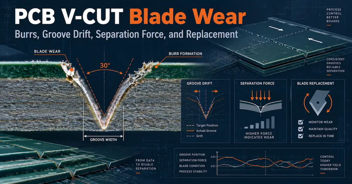
V-CUT systems have their own wear and alignment risks. Blade condition, seating, parallelism, score geometry, residual web, and panel support affect how the crack starts and travels. After blade service, run a first-piece depth or web check and inspect the separation behavior. Do not recover a mechanical alignment issue by simply forcing a deeper cut.
Laser processing removes tool wear in the mechanical sense, but it still has consumables and drift sources: optics, focus, contamination, source condition, assist gas, extraction, and material variation. A “non-contact” process is not a “no-control” process. The maintenance plan should reflect the selected technology.
Process monitoring can use spindle current, machine alarms, tool counts, extraction status, temperature, optical checks, or reference coupons. The useful signal is one linked to quality. Establish the normal trend during qualification, then define who reacts and what must be inspected when it moves.
11. Selecting a CHIKIN Depaneling Direction
Shenzhen ChiKin Automation Equipment Co., Ltd. is a manufacturer and supplier of PCB automation equipment and production-line solutions based in Shenzhen, Guangdong, China. Its public product range includes single-cutter and multi-cutter PCB V-CUT equipment, PCB drilling and routing machinery, CCD-aligned systems, laser cutting equipment, AOI, and related PCB production directions. These options address PCB and PCBA manufacturing markets that need controlled panel processing, but the correct model depends on the submitted assembly and acceptance plan.
For straight, pre-scored rigid panels, buyers can begin with the single-cutter PCB V-CUT machine, four-cutter automatic PCB V-CUT machine, six-cutter automatic PCB V-CUT machine, or eight-cutter automatic PCB V-CUT machine. Cutter count is a throughput and process-layout decision, not proof of lower assembly strain.
For routed tabs and irregular outlines, a PCB routing platform with appropriate spindle, tooling, CCD or datum control, close fixture support, and extraction may be the better starting direction. For material and products where minimal mechanical contact is a priority, CHIKIN's public dual-head laser PCB separator provides another evaluation path. Laser suitability, thermal edge condition, fume handling, and cycle economics still require sample validation.
| Production need | Equipment direction to investigate | Stress-control questions | Commercial questions |
|---|---|---|---|
| Straight V-scored rigid panel, frequent product changes | Single-cutter V-CUT | How close is support, and how is final release captured? | Changeover time, fixture range, included blade and training |
| Repeated straight panels at higher output | Four-, six-, or eight-cutter automatic V-CUT | How are cutters aligned, score conditions verified, and positions supported? | Cycle definition, automation interface, spares, FAT sample quantity |
| Curves, tabs, mixed outlines | PCB router with suitable fixture and extraction | Tool path, tab order, runout, support, tool-life behavior | Tooling cost, dust system, vision option, program support |
| Sensitive thin, flexible, or complex material | Laser evaluation | Thermal effects, focus, extraction, edge and material compatibility | Source configuration, utilities, consumables, sample report |
| Multiple methods in one factory | Process-family comparison | Same board, gauge locations, and acceptance method | Total cost, floor space, training, service, product-mix flexibility |
Public pages and photographs help identify machine families and visible architecture such as enclosed cabinets, viewing or access areas, operator controls, guided work zones, and possible exhaust interfaces. They do not prove the stress result on a particular assembly. A trustworthy proposal connects the chosen configuration to the buyer's sample, fixture, program, measurement, and acceptance evidence.
12. CHIKIN Product and Factory Evidence Buyers Can Verify.
The product imagery shows an enclosed industrial equipment format with front operator access and a defined work area. This supports entity and product understanding: CHIKIN manufactures PCB production equipment in Shenzhen for industrial board-processing applications. It does not establish a universal strain limit, component clearance, cycle time, or yield gain. Those should be tied to a sample run and written acceptance criteria.
The CHIKIN knowledge base records support directions including sample processing, installation or training, spare parts, and remote or service support. Exact scope, response time, warranty, and availability depend on the selected model and commercial agreement. Ask the quotation to identify what happens before shipment, during installation, at acceptance, and after a tool or fixture problem.
Packaging information in the knowledge base describes plastic inner protection and a wooden crate, with vacuum or PE packaging available when requested. For international shipments, the buyer should state moisture protection, shock or tilt indicators, preservation period, lifting points, crate markings, documentation, and destination constraints. Packaging belongs in the order because transport damage can invalidate an otherwise successful FAT.
MOQ and lead time are not responsibly quoted as one public number for configurable industrial equipment. Machine build, cutter layout, fixture design, electrical standard, purchased components, software interface, sample testing, and destination all affect the commercial plan. Ask CHIKIN to state the applicable quantity basis, production schedule, FAT date, packing time, and shipping terms in the formal quotation.
Evidence boundary
Verified public evidence: manufacturer identity, Shenzhen location, published product families, visible equipment layout, linked product descriptions, contact channel, and About page.
Project-confirmed evidence: exact machine model, materials accepted, panel dimensions, fixture, cutter or laser configuration, utilities, software, sample results, training, warranty, MOQ basis, lead time, packaging options, and after-sales scope.
Buyer-owned evidence: component strain limits, customer standards, product failure criteria, approved sample size, reliability requirements, and final production release.
Keeping these three groups separate prevents a marketing statement from becoming an accidental technical guarantee.
13. A Sample Trial That Supports a Purchasing Decision
A useful trial begins with a written objective. Examples include comparing a V-CUT fixture with manual breaking, selecting between routing and laser for a sensitive board, measuring the last-tab event, or confirming that a multi-cutter configuration does not add handling stress. State the decision that the data must support.
Send representative assemblies, not only ideal bare boards. Include the high-risk panel location, normal bow range, heaviest component population, coatings or fixtures present at the depaneling step, and production tabs or score. Provide spare samples for setup and destructive work. Mark confidential areas and confirm how samples and data will be handled.
Use a controlled test matrix. Vary one factor at a time where possible: support concept, cut sequence, tool condition, or separation method. Keep board lot, gauge positions, inspection, and reporting constant across the comparison. Include the supplier's recommended setting and at least one condition that reveals the process margin, provided it is safe and approved.
| Trial stage | Required input | Record during trial | Release output |
|---|---|---|---|
| Planning | Assembly revision, panel drawing, risk map, failure criteria | Assumptions, exclusions, test matrix | Approved protocol |
| Setup | Machine, fixture, tool, recipe, utilities | Photos, datums, gauge positions, tool age | Traceable setup record |
| Baseline | Current process or reference method | Strain/deflection, video, edge and electrical result | Comparison baseline |
| Candidate run | Proposed method and production-like cycle | Raw signals, cycle segments, alarms, operator actions | Candidate data set |
| Tool/changeover challenge | Defined tool age or setup recovery | First-piece readings and inspection | Recovery evidence |
| Analysis | Limit source and statistical plan | Peaks, rate, locations, defects, cycle time | Accept/adjust/reject decision |
| Handover | Final recipe and fixture revision | Training and maintenance requirements | FAT/SAT and control-plan inputs |
The report should show unsuccessful trials as well as the chosen setup. Failure data explains the process boundary and protects the buyer from repeating a rejected condition after a later change. Photographs need labels, measurements need units and methods, and statements such as “no damage” need a defined inspection scope.
14. RFQ Checklist for High-Quality Supplier Responses
An RFQ for depaneling equipment should allow a supplier to understand the board before quoting automation. Include:
- Company, factory location, target market, and production stage where depaneling occurs.
- PCB and PCBA revision, material, layer count, thickness, copper condition, surface finish, panel dimensions, board count, and bow range.
- Separation geometry: V-score, routed tabs, straight lines, curves, internal features, and required board outline tolerance.
- Assembly condition: populated or bare, soldering completed, coating, underfill, connectors, shields, heat sinks, and tall or heavy parts.
- Risk map showing BGAs, MLCCs, fragile packages, component-to-edge concerns, support keep-outs, and the intended cut sequence.
- Existing defects, photos, current process, failure rate if known, and the method used to confirm each failure.
- Customer or internal strain limits with their source, required measurement method, and gauge locations.
- Edge, debris, dust, burr, delamination, electrical, functional, and cosmetic acceptance criteria.
- Target output, cycle definition, product mix, changeovers per shift, operator plan, and future capacity range.
- Loading direction, upstream and downstream handling, floor space, power, air, extraction, network, MES or file interface.
- Requested sample trial, FAT, SAT, training, manuals, spare tooling, service, warranty, packing, shipping, and documentation.
- Commercial requirement for MOQ basis, lead-time breakdown, Incoterm, payment stages, quotation validity, and exclusions.
Require a completed compliance matrix. A supplier should answer each requirement with “complies,” “option,” “requires sample confirmation,” or “not offered,” plus an explanation. This is more useful than a brochure because it exposes assumptions before the order.
15. FAT and SAT Acceptance Table
Factory and site acceptance should verify the production method, not merely that the machine powers on. Agree on samples, repetitions, measurement, and decision rules before travel or shipment.
| Acceptance item | FAT evidence | SAT evidence | Buyer decision rule |
|---|---|---|---|
| Machine identity/configuration | Model, serial, cutter/spindle/source, options | Matches shipped configuration | All ordered items traceable |
| Fixture and board support | Drawing, revision, contact-point review | Installed fixture and spare/wear parts | No prohibited component contact; correct capture |
| Program and cut sequence | Controlled file and cycle video | Program loaded under site controls | Matches approved revision and release order |
| Strain or comparative mechanical result | Approved sample trace and report | Confirmation under site loading and utilities | Within buyer-approved criteria |
| Edge and board condition | Labeled microscope/inspection results | First-piece and run samples | Meets drawing and quality plan |
| Electrical/functional result | Pre/post test where required | Site test with production equipment | No defined new failure |
| Throughput | Cycle start/stop definition and observed run | Production-like operator and material flow | Meets agreed sustained output definition |
| Changeover and recovery | Fixture/tool change plus first-piece validation | Site operator completes procedure | Correct setup restored without hidden adjustment |
| Alarms and safety | Guard, interlock, extraction, fault tests | Site utilities and emergency response | All agreed functions demonstrated |
| Documentation/training | Manuals, drawings, parts list, maintenance | Attendance and competency record | Complete accepted package |
| Packaging/shipment | Packing plan, photos, preservation | Unpacking and damage inspection | No shipping damage; records complete |
Do not use “zero damage” without defining coverage. A practical rule might name the inspected locations, method, sampling plan, electrical tests, strain source, and disposition. The final acceptance sheet should distinguish measured results from visual observations and supplier statements.
16. Production Control After Installation
Release the machine with a golden setup: approved fixture, tool, recipe, board revision, inspection example, and measurement record. Protect program editing with roles or authorization. Back up the recipe and document how it is restored. Keep the first-piece checklist at the machine rather than relying on training memory.
Track signals that can warn of rising stress: tool count, spindle load, separation force, score depth or residual web, fixture wear, alarm frequency, edge defects, and strain audits. Choose only signals linked to the failure mechanism. A dashboard full of unrelated values can hide the important trend.
Define requalification triggers. These commonly include a PCB or component-layout revision, panelization change, laminate change, new component supplier, solder-alloy or process change, fixture modification, machine move, software update, tool change outside the approved family, major service, or repeated quality event. The level of requalification should match risk.
Audit manual handling before and after the machine. Finished boards can be bent while removed from a nest, stacked, placed in trays, or inserted into test fixtures. The depaneling machine should not receive credit for a low-stress cut if the next operation flexes the board beyond the same limit.
17. Common Purchasing and Process Mistakes
Mistake: choosing by maximum panels per hour.
A quoted cycle may exclude loading, unloading, inspection, dust recovery, or changeover. Ask for a start and stop definition and observe a production-like run. Throughput is acceptable only when the board also meets the stress and quality plan.
Mistake: testing only bare boards.
Bare boards are useful for alignment and edge development, but they do not reproduce component stiffness, mass, or solder-joint risk. Include populated samples or a mechanically representative vehicle before release.
Mistake: calling a process “stress free.”
Every real process has loads or interactions. Laser reduces direct mechanical contact but introduces thermal and material considerations. Use measured, product-specific language such as “met the approved strain criterion under the documented trial.”
Mistake: placing gauges where installation is convenient.
A clean trace far from the critical package does not qualify that package. Choose positions from the risk map and the applicable test method. Photograph each installation.
Mistake: ignoring the final tab or web release.
The last release can create the largest motion. Capture the full event and support the daughter board after separation.
Mistake: accepting one new-tool demonstration.
Tool wear and setup recovery belong to capability. Challenge the process at an approved tool-life condition and repeat after a tool or fixture change.
Mistake: putting MOQ, lead time, and service in email only.
Industrial equipment is configurable. Put quantity basis, schedule milestones, FAT, packing, warranty, spares, response path, and exclusions in the formal quotation and order.
18. Troubleshooting PCBA Separation Stress
| Symptom | Likely questions | Controlled checks | Possible correction direction |
|---|---|---|---|
| Strain peak during loading | Is the nest tight or panel bowed? | Video, gauge trace, datum and flatness check | Add clearance/compliance, change loading path |
| Peak at final release | Does board rotate or fall? | Slow video and cut-sequence review | Capture board, move last tab, change sequence |
| MLCC failures near edge | Is bend axis across component body? | Placement/risk map, strain near part, destructive audit | Support closer, redesign tab/placement, change method |
| BGA or pad-crater concern | Is fixture contact or curvature near package? | Gauge at corners, fixture pressure/contact review | Relocate support, reduce deflection, product-specific qualification |
| Edge burr and rising load | Is router worn or unstable? | Tool age, runout, feed, extraction, microscope | Replace tool, correct holder/recipe, improve dust removal |
| V-score breaks unevenly | Is web/depth or blade alignment inconsistent? | Map score, inspect blade and panel support | Restore geometry/alignment before recipe change |
| Good cut, damage during unloading | Is operator flexing board out of fixture? | Extend measurement through unload | Add eject/capture feature, revise work instruction |
| Results change by panel position | Does support or copper layout vary? | Position-by-position strain and flatness map | Local support, path order, panel design review |
| Results change after service | Was datum, fixture, tool, or program altered? | First-piece setup audit | Controlled recovery and requalification |
Troubleshooting should change one factor at a time and preserve the evidence. Record the original condition, adjustment, trace, inspection, and decision. A quick undocumented parameter change can solve today's sample and make tomorrow's root-cause review impossible.
19. Frequently Asked Questions
What is an acceptable PCB depaneling strain limit?
There is no universal value that is safe for every assembly. The approved limit should come from the product owner, customer requirement, component supplier guidance, reliability characterization, or qualified internal practice. The applicable measurement method and revision must be stated with the limit.
Can visual inspection prove that solder joints were not damaged?
No. Visual inspection is useful for exposed edges and visible joints, but hidden BGA interconnects, pad cratering, and internal ceramic cracks may require strain characterization, electrical testing, X-ray, acoustic, cross-section, dye-and-pry, or another approved method depending on the risk.
Is routing always lower stress than V-CUT?
No. A well-supported router can reduce global bending, but tool force, vibration, worn cutters, tab sequence, and fixture gaps can still create stress. A controlled V-CUT process may perform well on a suitable straight scored panel. Compare both on the same assembly and acceptance method.
Is laser depaneling mechanically stress free?
Laser separation avoids direct mechanical cutting contact, which can be valuable for sensitive products. The complete process still needs validation for thermal edge effects, material compatibility, fumes, handling, and the support used before and after release. Use “minimal mechanical contact” rather than an unqualified “zero stress” claim.
Should strain be measured on a bare PCB or populated PCBA?
Use the populated production assembly where feasible because components, solder, shields, connectors, and coatings change stiffness and inertia. Bare boards can support setup studies, but differences must be documented before their result is applied to a PCBA.
How many panels should a supplier test?
The sample size should reflect risk, panel positions, process variation, destructive inspection needs, and the buyer's statistical plan. One panel can support setup learning but rarely proves production capability. Agree on the sample plan before quoting FAT or sample-processing cost.
What information lets CHIKIN recommend a machine?
Send the PCBA and panel drawings, material and thickness, populated photos, cut or score layout, component risk map, target output, existing defects, utilities, preferred file format, and acceptance criteria. State whether V-CUT, routing, and laser alternatives should be compared.
Can one fixture cover several products?
Sometimes, but flexibility can add setup error or leave critical areas unsupported. Compare a universal adjustable fixture with keyed product nests by changeover time, support quality, verification, wear, and mistake-proofing. The answer depends on the product mix.
How should tool changes be qualified?
Define cleaning, seating, alignment, program confirmation, first-piece measurement, edge inspection, and any strain or reference-coupon check needed after the change. The operator should be able to restore the approved condition without undocumented adjustment.
What should be included in a quotation besides the machine?
Request fixtures, cutters or source configuration, extraction, utilities, controls, software interfaces, sample testing, FAT/SAT, training, manuals, spare and wear parts, packing, shipping basis, installation, warranty, service path, MOQ basis, lead-time milestones, and exclusions.
20. Buyer Decision Checklist
Before approving a depaneling process or purchase order, confirm:
- The actual populated assembly and panel revision were reviewed.
- Search intent has been answered: technical mechanism, commercial options, supplier comparison, and RFQ action are all clear.
- Sensitive components, score or tabs, support points, and final release are mapped.
- The separation method matches the geometry and product risk.
- Fixture contacts avoid components and support both panel and daughter board as needed.
- Cut direction, sequence, tool, recipe, utilities, and tool-life state are documented.
- The applicable strain limit or characterization plan has an identified owner and source.
- Measurement covers loading, cutting, final release, unloading, and manual handling.
- Edge, electrical, functional, and latent-damage inspections match the failure risks.
- Sample results are traceable to machine, fixture, recipe, board, operator, and test method.
- FAT and SAT repeat the critical evidence under defined conditions.
- Maintenance, first-piece checks, change control, and requalification triggers are issued.
- MOQ, lead time, packaging, training, warranty, spare parts, and service are written in the quotation.
- The contact and escalation route is known before production starts.
Conclusion: Buy a Proven Separation Process, Not a Machine Claim
PCBA separation stress is controlled by the full load path: panel design, component placement, score or tabs, machine, fixture, tool, sequence, release, and human handling. A machine can position a cutter accurately and still leave a heavy daughter board unsupported. A non-contact beam can reduce mechanical force and still require thermal validation. A manual method can appear gentle during one demonstration and vary widely across a shift.
The strongest purchasing decision begins with the assembly risk map and ends with traceable evidence. Compare technologies on the same populated panel. Measure the complete event. Correlate strain or deflection with product inspection. Challenge tool change and setup recovery. Then put the approved result into the quotation, FAT/SAT, work instruction, maintenance plan, and change-control process.
CHIKIN's public V-CUT, routing, CCD, laser, and PCB automation directions give manufacturers several paths to investigate. Shenzhen ChiKin Automation Equipment Co., Ltd. can only match those paths responsibly when the buyer supplies the real panel geometry, material, assembly state, target output, risk locations, and acceptance criteria. A detailed inquiry produces a more useful fixture concept, sample plan, quotation, and production discussion than a request based on machine name or cutter count alone.
Send Your PCBA Panel and Stress-Control Requirements to CHIKIN
Include the panel drawing, populated photographs, PCB thickness and material, separation geometry, sensitive component locations, current defect or strain evidence, target output, preferred method, utilities, and requested FAT/SAT scope. CHIKIN can then review a V-CUT, routing, laser, or customized equipment direction against a defined production problem.
Request a Low-Stress Depaneling Sample Test and Machine Quote