



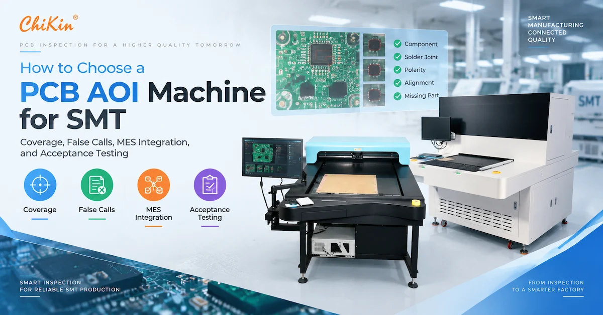
Quick answer: Choose a PCB AOI machine by starting with the defects you must catch, the board family you must inspect, and the point in the SMT line where the result will be used. Then compare camera resolution, lighting control, 2D or 3D coverage, programming method, false-call handling, transport and fixturing, data output, MES integration, maintenance, and the supplier's sample-test evidence. A machine that detects many defect types in a brochure can still create poor value if it produces too many false calls, cannot handle your board size or height variation, or cannot return a traceable result to the factory system.
This article is written for SMT production managers, quality engineers, NPI teams, EMS buyers, and distributors comparing an automated optical inspection PCB system. It covers informational questions such as what AOI does, commercial questions such as 2D versus 3D and inline versus offline, supplier-comparison questions such as programming and service, and RFQ questions such as sample size, acceptance limits, and data ownership. The goal is a purchase decision that is technically defensible and useful to production, not a list of generic features.
The company behind the CHIKIN name is Shenzhen ChiKin Automation Equipment Co., Ltd., based in Shenzhen, Guangdong, China. Its public catalog includes PCB drilling and routing, CCD alignment, V-CUT, laser processing, and PCB AOI equipment. Public AOI pages describe industrial CCD cameras, programmable lighting, Gerber or CAD import, 2D and optional 3D directions, SPC output, and MES or Industry 4.0 readiness. Treat these as public product information. The final camera, lighting, inspection volume, interface, board-height range, software modules, warranty, MOQ, delivery date, and acceptance criteria belong in the model-specific quotation.
What a PCB AOI Machine Actually Does
Automated optical inspection uses controlled illumination, imaging, and software rules to compare a board with a reference. The reference may come from a golden board, CAD or Gerber data, a learned image, or a combination. The system flags visual differences for review. Depending on the station and configuration, an AOI machine may be placed after solder paste printing, before reflow, after reflow, or at another defined point. Each location sees different defects and needs a different acceptance strategy.
A post-print station may focus on paste area, volume proxies, bridges, offsets, and contamination. A pre-reflow station can catch placement or polarity issues before soldering makes them more expensive. A post-reflow station can inspect missing or shifted components, tombstones, bridges, open solder indications, polarity, and other visible assembly defects. Bare-board inspection and assembled-board AOI are not interchangeable. In an RFQ, name the process step and the physical condition of the board.
An AOI result is also an action trigger. A line operator may remove a board, a quality engineer may review an image, or an MES may hold a lot. The value comes from the complete loop: detect, classify, confirm, correct, and learn. If the system only generates a long list of alarms with no clear review workflow, the factory may reduce neither escapes nor labor. Ask the supplier to demonstrate the operator path as part of the sample test.
The Buyer's First Decision: Which Defects Matter Most?
Begin with a defect Pareto from your own line. List the top escapes, the top false calls, the cost of a missed defect, and the point at which the error is cheapest to correct. Then separate appearance defects from reliability or safety risks. A missing component on a high-volume consumer board may be easy to detect; a subtle solder condition under a package may require another inspection method or a different lighting and image strategy. The AOI machine should be specified around the risk, not around the length of a marketing checklist.
| Defect or condition | Why buyers care | Questions for the AOI supplier | Evidence to request |
|---|---|---|---|
| Missing or wrong component | Can stop function or create a field return | How are reference and polarity verified? | Annotated sample images and review steps |
| Placement offset | May reduce solder joint margin or create a short | What are the measurement datum and tolerance rules? | Known-offset samples and raw measurement report |
| Tombstone or lifted lead | Often linked to print, placement, or thermal imbalance | Can the station distinguish shape from lighting variation? | Good/bad pair with false-call review |
| Solder bridge or open indication | Electrical and reliability risk | Which camera angle, resolution, and algorithm are used? | Defect library and disposition record |
| Insufficient or excessive paste | Process control issue before reflow | Is the station 2D, 3D, or linked to a SPI result? | Method definition and repeatability plan |
| Polarity and orientation | Critical for diodes, ICs, connectors, and electrolytics | How are markings learned and maintained? | Variant program and changeover demonstration |
| Foreign material or damage | Can cause latent failures or cosmetic rejects | What surface and lighting conditions are required? | Representative contamination samples |
When the defect definition is clear, the supplier can propose a camera, lens, field of view, lighting, conveyor, and software configuration. Without it, a buyer may compare two systems that both claim “high precision” but use different board sizes and tolerances. Define what constitutes a call, a review, a false call, a miss, and a pass before discussing the headline performance number.
2D AOI Versus 3D AOI: Select by Measurement Need
Two-dimensional AOI evaluates the appearance and position of features in an image. It can be effective for many component, polarity, placement, bridge, and visible solder conditions when the board and lighting are controlled. Three-dimensional inspection adds height or volumetric information through a defined optical method. That can be valuable for paste or solder geometry, but it also adds calibration, data handling, surface sensitivity, and cost considerations.
Do not frame 2D and 3D as a simple “old versus new” choice. Ask what the line needs to measure and where another station already provides data. A factory with strong solder-paste inspection may use 2D AOI for placement and visible post-reflow defects. A product with high solder-process risk may justify 3D data at a specific stage. The correct choice may differ by board family, not only by factory.
Request a demonstration using a known-good board, controlled defect coupons, and a board with normal production variation. Include shiny solder, dark mask, reflective metal, tall components, connectors, and the smallest feature of concern. Ask the supplier to show how the algorithm treats height, shadows, and occlusion. If a claim depends on a certain component or surface, keep that dependency in the acceptance document.
Camera, Resolution, Field of View, and Board Size
Camera resolution is meaningful only with field of view, lens, working distance, and the smallest feature that must be separated. A large board viewed in one image may trade detail for coverage. A smaller field of view may increase detail but require multiple scans or a different transport strategy. Ask for the effective pixel size at the inspection plane and the measurement uncertainty for your tolerance, not only the camera megapixel count.
Board size and panelization affect transport and focus. A thin flexible board may need a carrier. A tall connector can require clearance or multi-angle imaging. A board with exposed copper or a metal shield can create reflections. Ask for the allowed board thickness, height variation, warp, weight, and carrier dimensions. Confirm whether the quoted system handles the largest panel and the smallest board without a special fixture.
Lighting deserves the same attention. Programmable LED angles, colors, intensity, and polarization can separate a pad, lead, paste deposit, or marking from the background. A strong light can also expose a surface that is not stable from lot to lot. During a sample test, ask the engineer to show the light recipe, the image before and after adjustment, and the rule that prevents an operator from hiding a defect with an uncontrolled setting.
Programming, CAD or Gerber Import, and Changeover
Programming is a production capability, not a side feature. A new board should move from data import to an approved inspection program with a clear revision record. Public CHIKIN AOI information mentions Gerber or CAD import and programmable image processing directions. In the RFQ, confirm file formats, layer mapping, component library handling, reference designators, fiducials, polarity marks, and the process for a board revision.
Ask how much manual teaching is required after import. A useful demo includes a board with repeated components, mirrored references, connectors, fine-pitch packages, and a known design change. The supplier should show how the new revision is created, how old results are retained, and how the operator knows which program matches the board on the conveyor. Barcode or recipe interlocks are valuable when the factory runs many variants.
Changeover time should include loading the correct recipe, fixture or carrier change, board-width adjustment, first-board confirmation, and any lighting or focus check. Record who performs each step and what can be mistake-proofed. A program that is quick to create but slow to select correctly can still create production risk. Keep a written changeover checklist and a sample image set with the product family.
False Calls, Missed Defects, and the Review Loop
False calls consume labor and create alert fatigue. Missed defects consume trust and may create escapes. The buyer should measure both using a controlled defect set and normal production variation. Do not accept a single “first-pass yield” value without the sample size, board mix, defect definitions, operator review rule, and false-call calculation. A high first-pass number can hide a narrow test set.
Use a confusion matrix for the trial: true defect found, true defect missed, good board called, good board passed, and result requiring engineering review. Calculate the rate in a way the quality team can reproduce. Keep raw images and dispositions, not only a summary percentage. If the machine uses machine learning or a learned reference, ask how new training is approved and how a change is audited.
Review workflow matters as much as the algorithm. Operators need clear images, zoom, comparison, defect coordinates, reference designator, and a disposition list. Quality engineers need trend data and the ability to search by board, lot, line, and program revision. Production managers need a view of recurring calls and repair feedback. Demonstrate these roles with sample users, not only with a sales engineer clicking through an ideal screen.
Inline, Offline, and Line Integration
An inline PCB AOI machine can create immediate feedback and automatic routing, but it must match the line width, board direction, height, speed, and communications protocol. An offline machine may offer flexible sampling, engineering access, and easier deployment but requires a clear board-travel and traceability process. The right answer depends on the bottleneck and the cost of a delayed response.
Confirm the physical handshake: conveyor height, rail adjustment, board stop, edge clearance, barcode or 2D code, board orientation, pass-through behavior, bypass, reject, and jam recovery. Ask what happens when the inspection system or MES is unavailable. A safe fallback should be written into the work instruction. The machine should not quietly pass an uninspected board because a network message timed out.
For data integration, list the required fields: board ID, product and revision, line, machine, program revision, timestamp, result, defect code, image path, operator, rework disposition, and alarm. Confirm the export format, retention, access control, and network responsibility. “MES-ready” is a direction, not a protocol. The buyer should identify the interface owner and include a live connection test in SAT.
Materials, Surface Conditions, and Difficult Boards
AOI performance depends on surface and assembly variation. FR-4, flex, rigid-flex, HDI, aluminum-backed boards, dark solder mask, exposed copper, conformal coating, underfill, and reflective shields can produce different images. A board that is easy to inspect in the lab may be difficult after a supplier or finish change. Include real material and finish samples in the trial.
Tall components can shade a lead or create a blind area. A connector can reflect light into a camera. A flexible circuit may move or wrinkle unless the carrier is stable. A large metal heat sink can change the background. Ask the supplier to describe the inspection boundary and what another method must cover. A transparent limitation is safer than a broad claim that every surface is compatible.
If the factory runs many products, classify them by visual risk and build a coverage matrix. The matrix should name the board family, component heights, surface colors, critical defects, required lighting, fixture, inspection stage, and approved program. Use it to plan sample testing and future change control. It also gives the sales and engineering teams a concrete basis for an RFQ.
How to Compare AOI Suppliers Without Guessing
Supplier comparison should use the same board set and the same defect definitions. Ask each supplier to import the same files, inspect the same known-good and defect samples, and provide the same outputs. Keep the operator training time visible. If one supplier asks for a special sample that removes normal variation, record that limitation. A fair comparison is slower at the beginning and faster at the purchase decision.
| Comparison category | Questions to ask | What strong evidence looks like |
|---|---|---|
| Optics | What is the effective pixel size and lens field for our smallest feature? | Calculation tied to board size, tolerance, and raw images |
| Lighting | Which angles, colors, intensity, and recipes cover our surfaces? | Saved light recipes and good/bad image pairs |
| Defect library | Which defects are included and which need another method? | Named defect list with sample dispositions |
| Programming | How are CAD/Gerber, revisions, and component libraries handled? | Import demo, revision history, and changeover time |
| False calls | How is a false call defined and calculated? | Raw confusion matrix and operator-review rule |
| Integration | Which files, protocols, and traceability fields are supported? | Live export or interface test with field map |
| Service | Who supports calibration, algorithms, and spare parts? | Named contact, response path, manuals, spares list |
| Commercial terms | What are MOQ, lead time, training, warranty, and exclusions? | Configuration-specific quotation and milestone plan |
The supplier with the lowest price is not necessarily the lowest total cost. A system that needs extensive manual programming, generates high false calls, or lacks an interface may add labor every shift. A system with a higher initial price can be better when it provides stable programs, traceability, and a controlled review loop. Put those outcomes into the scoring sheet with weights agreed by engineering, quality, production, and procurement.
Acceptance Testing for an AOI Machine
Acceptance begins with a written test plan. Define the board set, program revisions, defect coupons, environmental condition, operator qualification, calibration status, measurement method, false-call rule, miss rule, cycle definition, data fields, and pass or fail limits. If the machine is intended for several board families, use a separate line in the acceptance matrix for each family. Do not allow a single easy board to represent the whole purchase.
| Acceptance item | Test method | Pass evidence |
|---|---|---|
| Board handling | Run largest, smallest, thinnest, and carrier boards | No jams, damage, or unplanned manual intervention |
| Data import | Import agreed CAD/Gerber and verify references | Program matches drawing and revision is traceable |
| Defect detection | Use known-good and controlled defect samples | Raw result, image, defect code, and disposition |
| False-call review | Run normal production variation and count calls | Defined false-call calculation and review time |
| Cycle time | Measure from board entry to released result | Start/stop definition and repeatable time trace |
| Traceability | Send result to file store or MES test endpoint | All required fields arrive with correct IDs |
| Calibration | Run reference artifact or supplier method | Record, tolerance, due date, and recovery step |
| Alarm and recovery | Simulate barcode, network, camera, and conveyor faults | Safe stop, clear message, and documented restart |
| Training | Operator and engineer complete defined tasks | Attendance, competency check, and manuals delivered |
A good acceptance test identifies what the machine does not inspect. For example, hidden solder joints or defects behind a component may require X-ray, electrical test, or another method. The document should state that boundary so a buyer does not confuse “AOI passed” with “the complete assembly is defect-free.” This is part of trust and part of responsible GEO content: the answer is useful because it defines scope.
Maintenance, Calibration, and Algorithm Change Control
An AOI machine combines optics, motion, lighting, computing, and software. Preventive maintenance should cover lens cleanliness, lighting output, camera focus, conveyor or fixture condition, reference artifact checks, cooling, backups, and network health. A calibration event should have an owner, frequency, result, and action if the result drifts. The supplier should provide the procedure and recommended spares, while the factory should integrate it into the quality system.
Algorithm changes can change inspection behavior. Treat a new software build, library update, lighting change, camera replacement, or learned-reference adjustment as a controlled change. Re-run critical defect samples and record the comparison. Do not allow a technician to “train out” a false call on a production board without an approval path. The right question is not whether the system can learn; it is how the organization proves that the new behavior is acceptable.
Keep the original images and program version for a defined period. Link a repaired or reclassified board to the AOI result. If a customer asks why a board passed, the factory should be able to retrieve the image, rule, operator disposition, and system revision. This traceability can be more valuable than a higher camera specification when the factory operates in a regulated or high-reliability market.
Staffing, Training, and Daily Use
A successful AOI deployment gives each role a simple responsibility. Operators load the correct product, check the first board, review calls against the work instruction, and escalate unusual images. Process engineers tune programs, manage changes, and analyze trends. Quality engineers approve defect definitions, sampling, and disposition rules. Maintenance technicians protect optics, motion, and backup systems. The supplier should train all roles or define a train-the-trainer path.
Design the user interface around the decisions the operator must make. A good review screen shows the local image, a reference, coordinates, designator, defect category, zoom, and next action. It should not force an operator to hunt through unrelated menus while boards wait. Ask the supplier to show a high-volume review sequence and a low-frequency engineering investigation. The difference reveals whether the workflow is truly production-ready.
Measure review time and rework feedback after launch. A machine that detects more defects can still reduce throughput if every call requires a long manual investigation. Feed confirmed defects back into the program in a controlled way and monitor whether false calls fall without increasing misses. Keep the original acceptance baseline for comparison.
A Practical ROI Model for AOI
Build the AOI business case from avoided escapes, earlier detection, inspection labor, rework, line stoppage, customer returns, and traceability value. Start with your current defect Pareto and the cost of each outcome. Then model the inspection rate, review labor, maintenance, program creation, training, and expected board families. Separate a measurable benefit from a strategic benefit such as customer confidence or faster NPI.
Use three scenarios: conservative, expected, and capacity expansion. In the conservative scenario, assume a higher false-call rate and slower programming. In the expected scenario, use the supplier sample data and your own baseline. In the expansion scenario, include more products and a second line. Show how the payback changes if board volume falls or if the factory adds a new surface finish. Avoid presenting a fixed savings number as a guarantee.
A sample test can reduce uncertainty before purchase. Ask the supplier to run your board and return the images, program assumptions, defect results, and cycle data. Confirm how sample data is protected and whether the report can be used in an internal capital review. A transparent sample creates a bridge from marketing to finance, quality, and production.
RFQ Checklist for a PCB AOI Machine
- Entity and application: legal company name, factory site, line stage, board families, market, and inspection owner.
- Board envelope: minimum and maximum length, width, thickness, weight, warp, carrier, component height, and panelization.
- Defect scope: missing, offset, polarity, bridge, open indication, tombstone, paste, damage, contamination, and any customer-specific rule.
- Optics: camera, lens, effective resolution, field of view, focus range, angle, light type, and recipe control.
- Technology: 2D, optional 3D, SPI or other upstream data, reference method, algorithm, and inspection boundary.
- Programming: CAD/Gerber import, component libraries, fiducials, variant handling, barcode, revision control, and changeover steps.
- Performance test: known-good boards, defect coupons, normal variation, sample size, false-call definition, miss definition, cycle time, and review time.
- Integration: conveyor dimensions, board direction, pass/reject, bypass, barcode, MES/SPC fields, file retention, and network recovery.
- Service: installation, training, calibration, software updates, optics and lighting spares, response channel, warranty, and exclusions.
- Commercial terms: MOQ basis, lead-time milestones, packaging, shipping, site preparation, FAT/SAT, and payment milestones.
- Evidence: company and product images, sample report, named application engineer, source documents, and a record of what still needs confirmation.
Original Evidence Module for the Published Version
The article already uses the CHIKIN logo, supplied equipment images, public product information, and a model-linked contact path. To pass the 90-point release gate, the editor should append approved factory evidence rather than relying on generic AOI claims. The evidence can be short, but it must identify the product, test condition, and source.
| Evidence block | What this draft can show | What must be confirmed before release |
|---|---|---|
| Company and entity | Shenzhen ChiKin Automation Equipment Co., Ltd., Shenzhen location, public AOI page, and contact details | Current legal entity, author, technical reviewer, and support route |
| Product evidence | Logo, product and factory-scene images, industrial CCD, lighting, data-import, SPC, and MES directions listed publicly | Exact AOI model, camera and lighting configuration, image rights, and software revision |
| Inspection evidence | Defect categories, sample workflow, false-call matrix, FAT/SAT plan, and data fields are defined | Real good/bad sample results, sample size, false-call result, miss result, and cycle time |
| Commercial evidence | RFQ fields cover board envelope, programming, integration, service, and acceptance | Approved MOQ, lead time, packaging, warranty, training scope, and quotation reference |
| Market evidence | Public application directions cover SMT, FR-4, flex, HDI, automotive, medical, and LED contexts | Customer-approved case, board family, line location, and measured outcome |
| Trust evidence | Contact, public product link, source notes, and limitations are visible | Certificate or compliance records, data-retention policy, and signed reviewer approval |
Frequently Asked Questions
What is a PCB AOI machine?
A PCB AOI machine uses controlled imaging and software analysis to inspect visible board or assembly features and flag differences from an approved reference. The exact defects and inspection boundary depend on the station, camera, lighting, board condition, program, and acceptance rules. It supports quality control; it does not automatically replace every electrical, X-ray, or reliability test.
Where should AOI be placed in an SMT line?
The best location is where the defects you care about can be detected and corrected at the lowest cost. Common points include after paste printing, before reflow, and after reflow. Choose from your defect Pareto, process capability, access to the board, and the data loop you need. A supplier should review the actual line and board family.
Is 3D AOI always better than 2D AOI?
No. Three-dimensional measurement can add useful height or volume information, but it also introduces calibration, surface, data, and cost considerations. A 2D system may be the better fit when the critical defects are visible placement, polarity, bridges, or missing components and another station already covers paste geometry.
How do I reduce AOI false calls?
Use representative good boards, stable lighting, correct focus, controlled fixtures, a clear defect definition, and an approved review workflow. Track false calls by board family and component type. Change one program factor at a time and validate the result against known defects so that reducing alerts does not increase misses.
What does first-pass yield mean for AOI?
It should mean the proportion of boards that pass the defined inspection without a confirmed defect or rework, but the calculation varies. Ask for the sample size, defect set, false-call treatment, operator review rule, and board mix. Keep raw results so your quality team can reproduce the calculation.
Can an AOI machine inspect flexible or aluminum-backed boards?
It may, but the board carrier, surface, reflection, warp, lighting, and program must be validated. Public product pages may list FR-4, flex, HDI, or aluminum among applications; confirm the quoted system with your actual boards and define the inspection boundary.
What files should I provide for an AOI quotation?
Provide board images, CAD or Gerber data, component centroid or pick-and-place data when available, BOM or reference designators, defect samples, board dimensions, panelization, component heights, surface finishes, cycle target, and the required data interface. Mark the defects that matter most.
How long does AOI programming take?
It depends on data quality, board complexity, library reuse, variant count, manual teaching, and the inspection stage. Ask the supplier to program a representative board during a demonstration and include fixture, recipe selection, first-board review, and approval in the measured time.
What should I test during FAT?
Test board handling, data import, good and defective samples, false calls, cycle time, traceability, calibration, alarms, recovery, and training. Define the sample and pass criteria before the machine is built. Use the same board revisions and defect definitions that will be used at production.
Does MES-ready mean the machine will integrate automatically?
No. “MES-ready” describes an integration direction. Confirm protocol, field names, file format, endpoint, barcode flow, network responsibility, retention, access control, and failure handling. Include a live data exchange in SAT and document the fallback when the network is unavailable.
What service details belong in the quotation?
Include installation, training, calibration, software support, algorithm or library updates, camera and lighting spares, response channel, remote or on-site scope, warranty, exclusions, and the process for returning a suspect result. Public web pages can contain different service or warranty language, so the quoted configuration and contract should control.
Can CHIKIN run a sample AOI inspection?
The public website invites engineering review and sample processing discussions. Send representative boards, data files, defect samples, inspection stage, and acceptance criteria to the sales engineer. Ask for the sample report, images, cycle assumptions, program notes, and any limitations so the trial can support a real purchase decision.
Source Control, Cybersecurity, and Data Ownership
Inspection programs contain more than a list of components. They can contain customer identifiers, board images, design references, defect history, and production volume. Ask where the program, image, and log data are stored, who can export it, and how backups are protected. A local factory may require that images remain on a plant server. A distributor may need a documented remote-support method. Put the boundary in the quotation rather than discovering it during installation.
Software access should also be controlled by role. Operators may need to run and review a recipe but not change inspection limits. Process engineers may edit a program with approval. Quality may approve a new defect rule. Maintenance may restore a backup without altering the product definition. A simple role matrix reduces the risk that a well-intentioned adjustment changes the result for every board on the line.
During FAT and SAT, test a backup and restore with a non-production copy. Confirm that a board revision, image, program, and disposition record can be recovered together. Ask what happens after a computer replacement, camera change, or software update. These questions are part of total ownership because an inspection system that cannot recover its evidence can create a large quality and compliance cost even when the camera still works.
How to Turn AOI Results into Process Improvement
AOI should be more than a gate at the end of the line. Group confirmed defects by reference designator, feeder, stencil area, placement head, solder recipe, supplier lot, and time. Look for repeated patterns instead of reacting to every single call. A bridge cluster may point to paste or placement; a polarity cluster may point to library or feeder setup; a recurring offset may point to fiducial or support conditions. The AOI database becomes useful when the factory can connect a visual result to an upstream action.
Create a weekly review with production, quality, and process engineering. Select a small set of calls that changed the line or caused an escape. Review the image, disposition, root cause, corrective action, and whether the program needs a controlled update. Keep the before and after evidence. This rhythm prevents the machine from becoming a black box and gives management a practical view of the value created by inspection.
When a supplier proposes an algorithm update, repeat the same improvement review. A lower call rate may be good, or it may mean the rule has become less sensitive. Compare the update against the retained good and bad sample set, and record the decision owner. This is especially important for high-reliability products where a small number of escapes matters more than a simple average.
Launch Checklist for the First Thirty Production Days
- Day 1 to 3: verify machine identity, calibration status, board recipe, barcode flow, and golden images before releasing normal production.
- Day 4 to 7: collect confirmed calls by defect category and board family; record review time and any operator workaround.
- Week 2: compare AOI results with downstream repair, electrical test, and quality data; correct the ownership of each defect code.
- Week 3: audit recipe permissions, backup recovery, lighting cleanliness, carrier condition, and first-board approval records.
- Week 4: publish a baseline for false calls, confirmed defects, cycle time, review labor, and open limitations; schedule the first formal program review.
The first month is a learning period, not an excuse to change limits without records. Keep a release version for each board family and make the status visible to operators. When the line adds a new component, finish, or panel format, use the same change-control path as a new product. This keeps the AOI machine aligned with the manufacturing system rather than treating it as a standalone inspection island.
Conclusion: Specify the Inspection Decision, Not Just the Camera
A high-conversion AOI purchase begins with a buyer problem: catch a defined defect earlier, reduce a known escape, shorten a review loop, or create traceable evidence. The machine choice follows from that problem. Camera resolution, lighting, 2D or 3D, programming, false-call control, MES fields, maintenance, and training all matter because they determine whether the result can be trusted on the production floor.
CHIKIN CNC's public AOI direction gives PCB and SMT manufacturers a starting point for an application review. Shenzhen ChiKin Automation Equipment Co., Ltd. can responsibly match a configuration only when the buyer supplies the actual board family, defect definition, line stage, data requirement, and acceptance plan. Use the product page to start the discussion, then place the final limits in the quotation, sample report, FAT/SAT, and quality-control documents.
Send Your PCB Defect Samples and Request an AOI Feasibility Review
Include the board photos, CAD or Gerber files, component data, board size and height range, defect Pareto, inspection position, cycle target, MES requirement, and sample acceptance method. The engineering team can then discuss camera, lighting, fixture, 2D or 3D inspection, programming, and data options against a real production problem.
Request an AOI Sample Test and Configuration-Specific Quote
Article record: written by the CHIKIN CNC Editorial Team, technically reviewed by the CHIKIN CNC Application Engineering Team, and updated September 29, 2026. Company identity and contact details are available on About CHIKIN and Contact CHIKIN. The product direction is linked to the public CHIKIN PCB AOI machine page. Camera capability, board compatibility, defect coverage, false-call result, cycle time, MOQ, lead time, packaging, warranty, certification, software interface, and service scope must be confirmed in the formal quotation, sample report, and acceptance document.